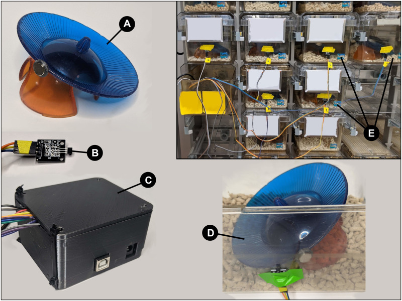
Fig 1.
A. The magnet attached to the wheel and hut. B. The Hall effect sensor, connected via wires to the Arduino. A red LED indicates when the sensor detects a magnet. C. The 3D-printed housing for the Arduino and breadboard, with wires for six sensors leaving the enclosure. D. Aligning and connecting the Hall effect sensor to overlap the rotation path of the magnet inside the cage. E. Example of the system connected to 6 cages. The wires are all leading back to the Arduino, which is connected via USB to a laptop.

