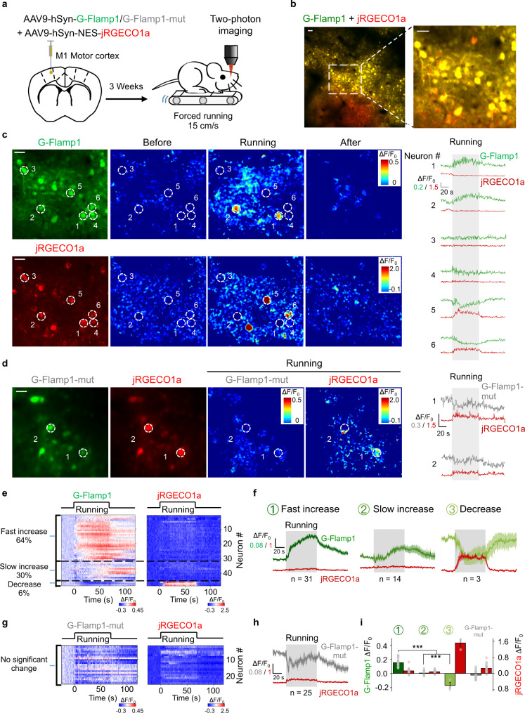
Fig. 4. G-Flamp1 reveals forced running-induced cAMP signals of neurons in the mouse motor cortex through in vivo two-photon imaging.
a Schematic diagram depicting the head-fixed mice on a treadmill together with two-photon imaging of the motor cortex co-expressing G-Flamp1 (or G-Flamp1-mut) and jRGECO1a. b Two-photon imaging of the mouse motor cortex co-expressing G-Flamp1 and jRGECO1a. The fluorescence of G-Flamp1 (green) and jRGECO1a (red) was merged and shown in yellow pseudo-color. Scale bars: 50 μm. c Representative images of probe expression in mice (left), the pseudo-color images (center) and the traces (right) of ΔF/F0 in response to forced running. White dashed circles with a diameter of 20 μm indicate selected ROIs covering soma for analysis. Scale bars: 30 μm. d Representative images of probe expression in mice (left), the pseudo-color images of ΔF/F0 (center) during the forced running phase and the traces of ΔF/F0 (right) in response to forced running. The white dashed circles with a diameter of 20 μm indicate selected ROIs covering the soma for analysis. Scale bar: 30 μm. e Heatmaps of G-Flamp1 and jRGECO1a responses during running task. Each row denotes a single cell’s response. n = 48 cells from three mice. f Averaged traces of ΔF/F0 for G-Flamp1 and jRGECO1a for neurons from three groups of different cAMP dynamics. n = 31, 14 and 3 cells for fast increase, slow increase and decrease groups, respectively. g Heatmaps of G-Flamp1-mut and jRGECO1a responses during running task. n = 25 cells from three mice. h Averaged traces of ΔF/F0 for G-Flamp1-mut and jRGECO1a during forced running process. i Quantification of the average ΔF/F0 during the first 30 s after the onset of forced running for G-Flamp1, G-Flamp1-mut and jRGECO1a in e, g. n = 31, 14, and 3 neurons from three mice for groups 1, 2 and 3, respectively. n = 25 from three mice for G-Flamp1-mut group. Two-tailed Student’s t-tests were performed. ***P < 0.001.Quantifications are shown as mean ± SEM in f, h, i with shaded regions or error bars indicating the SEM. Source data are provided as a Source Data file.

