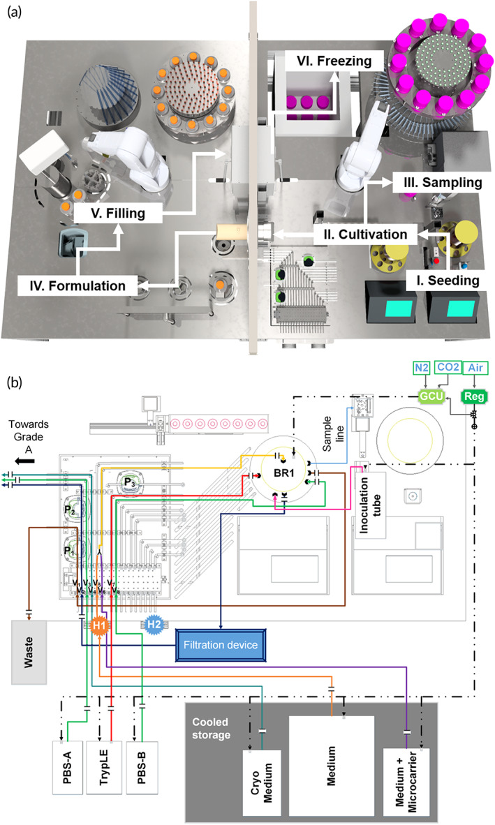
FIGURE 2.

Complete manufacturing process mapped out on the AUTOSTEM system and liquid flow on the platform. (a) Illustration of the production process steps along the different stations on the facility, including I: Seeding of the cells into the bioreactor; II/III: Cultivation, Sampling and Harvesting; IV and V: Formulation and Filling to VI. Freezing of the final cell product in the −80°C freezer. (b) Illustration of the tubing organization between bioreactor, media reservoir, waste and grade A area. For better usability, each line has been assigned a different color. Solid lines: liquid; dashed lines: gas; H1: Heater 1; H2: Heater 2; BR1: Bioreactor 1; GCU: gas control unit, Reg: gas regulator; P1‐3: Peristaltic pump 1–3, V1‐8: squeeze valve 1–8.
