
FIGURE 11.
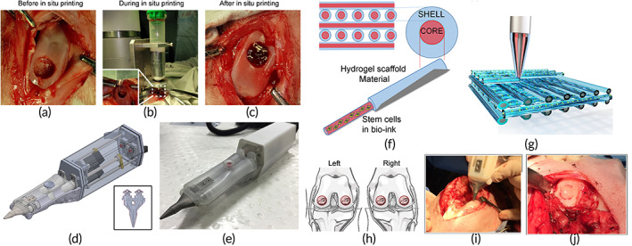
(a–c) In situ 3D bio‐printing applied to a rabbit's knee joint. Source: reprinted with permission from reference 59 . (d) The Biopen's design, which exhibits two distinct chambers controlled by a motor. The printing nozzle (insert) is linked to the two chambers, allowing for coaxial printing of the two distinct bioinks in a core/shell distribution. (e) A picture of the Biopen. (f) Core/shell distribution representation. The photo‐initiator VA086 for UV photocuring is included in the GelMa and hyaluronic acid methacrylate hydrogel (HAGelMa) in the shell, which provides mechanical support to the printed biomaterial while also protecting the inner core. Photo‐initiator is not present in the HAGelMa in the core, but it does contain mesenchymal stem cells. (g) A crisscross pattern is used to represent the multiple layer 3D‐printed block. (h) Both stifle joints have a full‐thickness chondral deficiency in the weight‐bearing region of the medial and lateral femoral condyles. (i) Photographs of the Biopen in use taken during surgery. (j) A bio‐scaffold is used to fill the defect, which is then covered with fibrin glue spray. The circular defect is evident, and it is macroscopically entirely filled while retaining the femoral condyle's apparent curvature. Source: (d–j) reprinted with permission from reference 52