

Abstract

The graphite–water interface provides a unique environment for polypeptides that generally favors ordered structures more than in solution. Therefore, systems consisting of designed peptides and graphitic carbon might serve as a convenient medium for controlled self-assembly of functional materials. Here, we computationally designed cyclic peptides that spontaneously fold into a β-sheet-like conformation at the graphite–water interface and self-assemble, and we subsequently observed evidence of such assembly by atomic force microscopy. Using a novel protocol, we screened nearly 2000 sequences, optimizing for formation of a unique folded conformation while discouraging unfolded or misfolded conformations. A head-to-tail cyclic peptide with the sequence GTGSGTGGPGGGCGTGTGSGPG showed the greatest apparent propensity to fold spontaneously, and this optimized sequence was selected for larger scale molecular dynamics simulations, rigorous free-energy calculations, and experimental validation. In simulations ranging from hundreds of nanoseconds to a few microseconds, we observed spontaneous folding of this peptide at the graphite–water interface under many different conditions, including multiple temperatures (295 and 370 K), with different initial orientations relative to the graphite surface, and using different molecular dynamics force fields (CHARMM and Amber). The thermodynamic stability of the folded conformation on graphite over a range of temperatures was verified by replica-exchange simulations and free-energy calculations. On the other hand, in free solution, the folded conformation was found to be unstable, unfolding in tens of picoseconds. Intermolecular hydrogen bonds promoted self-assembly of the folded peptides into linear arrangements where the peptide backbone exhibited a tendency to align along one of the six zigzag directions of the graphite basal plane. For the optimized peptide, atomic force microscopy revealed growth of single-molecule-thick linear patterns of 6-fold symmetry, consistent with the simulations, while no such patterns were observed for a control peptide with the same amino acid composition but a scrambled sequence.
Introduction
Self-assembly is an efficient and inherently scalable route to constructing devices from single molecules; however, the major challenge is the upfront design of molecular components that form desired structures with high fidelity. Polypeptides have many advantages as components of self-assembling functional materials, including their well-understood structural motifs, the biological and biotechnological infrastructure that exists for their synthesis and characterization, and the physicochemical diversity conferred by the 20 natural amino acids.1 Many studies have focused on constructing nanostructures from self-assembling proteins or peptides consisting of mainly α-helices,2,3 β-sheets,4 or collagen-like triple helices.5,6 There has been much interest in amyloid materials, which consist of peptides that form fibrils consisting of predominantly β-sheet structure.7−9 Branched amphiphilic peptides with structures analogous to phospholipids have been shown to form bilayers in water somewhat similar to lipid membranes,10 while peptides conjugated to aliphatic chains can assemble into a variety of structures including micelles, ribbons, and nanofibers.11−13
Two-dimensional materials, such as graphene, hexagonal boron nitride, and transition-metal chalcogenides, are promising materials for nanotechnology and can serve as substrates to guide growth of self-assembling structures. The presence of two-dimensional materials, such as graphene and its derivatives, can modulate peptide assembly.14−18 Facets of highly crystalline solids can also provide a substrate for quasi-two-dimensional peptide assembly. Under ultrahigh vacuum, ordered self-assembled peptide structures have been observed by scanning tunneling microscopy by Abb et al.19 on Au(111) surfaces and by Chen et al. on Cu(111) surfaces.20 Cryo-electron microscopy has been used to obtain atomic resolution structures of self-assembled peptoid arrays in water.21
As compared to three-dimensional assemblies, quasi-two-dimensional architectures have several desirable qualities. First, the structures can be more easily imaged by techniques such as atomic force microscopy. Second, the reduced dimensionality favors ordered structures by restricting conformational and orientational freedom. Finally, two-dimensional arrangements are typically easier for human minds to comprehend, facilitating intuitive design.
In previous work,22 we discovered that adsorption of a small peptide (Ac-Ala-NHMe, often called alanine dipeptide) to graphite considerably alters the conformational preferences of its backbone. In solution, the first of the two most probable conformations of Ac-Ala-NHMe is similar to the backbone conformation of a β-sheet or polyproline II helix, associated with Ramachandran angles of (ϕ, ψ) ≈ (−60°, 140°), while the second is typical of α-helices.23,24 However, at the graphite–water interface, two additional free-energy minima appear at (−150°, 160°) and (−170°, 0°) that are more favorable than these standard conformations.22 We refer to these new conformations as planar β and planar α, respectively, owing to the near coplanarity of their amide groups, which are stabilized at the graphite surface through amide−π stacking.25
The planar α and planar β conformations, illustrated in Figure 1A,B for Ac-Ser-NHMe, provide ordered motifs that could be used to construct quasi-two-dimensional peptide architectures. In particular, the planar β conformation has the potential to form continuous extended arrangements, similar to antiparallel β-sheets, but lacking the latter’s characteristic pleats. Hence, here we describe the computational design of peptides the form such “planar β-sheets”, along with experimental characterization of the self-assembled structures.
Figure 1.

Amino acids show varying propensities to form planar backbone conformations at the graphite–water interface in temperature replica-exchange simulations. (A,B) Capped serine (Ac-Ser-NHMe) typically adopts conformations in which both backbone amide groups lie flat against the graphitic surface. A water molecule appears to stabilize the arrangement of NH groups in the planar α conformation. Graphite is shown as gray spheres. The peptide is shown in a bond representation with the following colors: H, white; C, green; N, blue; and O, red. (C) Capped tryptophan (Ac-Trp-NHMe), on the other hand, adopts conformations where the side chain instead forms a π–π stacking interaction with the graphitic surface. (D) Fraction of time that both amide groups make contact with the graphitic surface for 20 capped amino acids and protonated histidine (H+) during replica-exchange MD simulations. (E,F) Ramachandran plots for Ac-Ser-NHMe and Ac-Thr-NHMe in simulation frames where both amide groups make contact with the graphitic surface. (G) Fraction of the total simulation in which each capped amino acid adopts a planar β-conformation.
Results and Discussion
Amino Acid Preferences for Planar Conformations
It has been shown that aromatic amino acids, particularly tryptophan and tyrosine, exhibit the highest affinity for the graphene–water interface.26,27 In addition, arginine has an affinity for this interface that is similar or perhaps stronger26 than tryptophan and tyrosine, which is likely related to the strength of guanidinium−π interactions.28 On the other hand, the carboxylates (glutamate and aspartate), alcohols (serine and threonine), and small aliphatics (alanine and valine) have the weakest affinity.26,27 Likewise, we find that different amino acids exhibit different preferences for planar conformations at the graphite–water interface. For example, as shown in Figure 1A,B, we find that capped serine (Ac-Ser-NHMe) typically adopts configurations where both amide groups lie flat on the graphite surface and the side chain points away from the surface. When the side chain has a high affinity for the interface, such as the case of tryptophan, the Ac-X-NHMe molecule almost never adopts a backbone-stacked configuration (Figure 1C). To design peptides that would adopt planar β-sheet conformations,22 we estimated the propensity of each canonical amino acid in the context of Ac-X-NHMe molecules to adopt a planar conformation at the graphite–water interface using temperature replica-exchange MD simulations.29 Both neutral and positively charged histidine were included. Figure 1D shows the fraction of the simulation at the base temperature (295 K) where both amide groups were stacked atop the graphite (using the criterion that the distance between the center of mass of each amide group and upper graphene layer was <0.42 nm). We find that there is a competition between the backbone and the side chain for the graphitic surface. Compact hydrophilic side chains that interact weakly with the graphitic surface, such as those of Ser, Ala, Asp, and Thr, tend to adopt configurations where both amides form amide−π stacking interactions. Conversely, side chains that show a high affinity for the graphite–water interface, such as those of aromatic amino acids Trp, Tyr, and Phe, outcompete the backbone and adopt configurations similar to those shown in Figure 1C.
Serine appears most compatible with planar backbone conformations; however, as evidenced by the Ramachandran plot in Figure 1E, Ac-Ser-NHMe spent roughly equal time in planar β- and planar α-conformations (39% and 32%, respectively). On the other hand, as shown in (Figure 1F), threonine appears to overwhelmingly favor planar β over planar α (45% versus 9%). In fact, Ac-Thr-NHMe spent more time in the planar β-conformation than any other amino acid (Figure 1G). All in all, Figure 1G suggests that Thr, Asp, Ser, Ala, and Gly are the best choices for designing peptides that adopt planar β-conformations.
Hairpin Design
The planar β-conformation involves a nearly 180° rotation of the backbone between each α carbon; therefore, if the peptide shown in Figure 1B were extended beyond a single amino acid, the side chain of the second amino acid would point into the graphitic surface, and steric interaction with the graphite would preclude planar backbone structure. Hence, to create a continuous planar β-strand on graphite, the sequence must alternate between an arbitrary amino acid and glycine (or, alternatively, D-amino acids). Here, our designs are based on GX repeats, where X is an arbitrary amino acid typically chosen from T, D, S, A, and G. Interestingly, GX repeats are sometimes found in nature, including GA repeats in silk proteins.30
We began by designing β-hairpins consisting of two GS-repeat planar β-strands joined by a 180° turn. The turn sequence was first chosen as GGGG, which gives the most conformational flexibility, and which was then optimized in Rosetta,31 yielding a GDGG turn. Rosetta also suggested the replacement of one GS repeat with a GD repeat to give the sequence SGDGSGSG-GDGG-GSGSGSGS (the turn is set off by hyphens). This structure is shown in Figure 2A. The behavior of the peptides was studied in simulated annealing MD simulations, where peptides were placed on the graphite surface, melted at high temperature (590 K), and gradually cooled to 370 K over 300 ns, at which temperature the simulation was continued for 2 μs. We chose 370 K instead of room temperature to accelerate conformational transitions and make it easier to observe folding; however, with the final peptide we confirm the stability of the folded state at 295 K using replica exchange. Simulations of the 20-mer peptides based on GS repeats and the GDGG turn showed formation of β-strand structures; however, the arrangements were quite disordered (Figure 2B). Some hairpins (cyan carbons) were formed, but alignment of β-strands varied and did not match Figure 2A.
Figure 2.

Spontaneous formation of planar β-strand structures in simulations where the peptides initially adopted unfolded structures. (A) Intended hairpin structure for a peptide with standard N- and C-termini. (B) Self-assembly of molecules of this peptide in a 2 μs molecular dynamics simulation. (C) Intended structure for a disulfide-cyclized peptide. (D) Self-assembled structure of this peptide in 2 μs. (E) Intended structure for a head-to-tail cyclized peptide. (F) Self-assembled structure of this peptide in 2 μs. Peptides folded into the intended structure are shown with green carbons. Misfolded hairpins are shown with cyan carbons. Other conformations are shown with purple or light yellow carbons.
Cyclization of peptides by disulfide bridges can stabilize short β-hairpins in solution,32,33 although the geometry imposed by the disulfide bridge is not quite optimal for β-strands.34 Hence, our next step was to add a disulfide bridge to the termini, to form an expected conformation like Figure 2C (sequence CGDGSGSG-GDGG-GSGSGSGC). This expected conformation (green carbons) spontaneously appeared in some cases (Figure 2D). However, not all of the molecules formed β-strands on the time scale of the simulation (2 μs), and some of the β hairpins were misaligned (cyan carbons) relative to the desired structure. In a common “misfolded” conformation, neighboring residues in the β sheet were shifted by two residues, making the hairpin turn GGDG, rather than the desired GDGG turn.
Another method for improving the stability of the β sheets, which may have a more favorable geometry than disulfide cyclization, is head-to-tail linkage of the N- and C-termini. One disadvantage of N-to-C linked peptides is that all residue positions are equivalent, making it more difficult to design favored locations for β-turns to form. To create a unique β-strand alignment, we sought sequences that would force the turn to occur at the desired locations. Two consecutive nonglycine residues, such as Ser-Asn, disrupt the planar β-strand conformation and can force a turn. As described below, we later found that proline residues32 might be more suitable for forcing turns. Using Rosetta, we designed an N-to-C cyclic peptide, with turns including two nonglycine residues. We also restricted Rosetta from using amino acids that may be charged at typical accessible pH values (D, E, H, K) to simplify theoretical considerations. We included one cysteine, which was added to facilitate future conjugation of the peptide (although we have not yet taken advantage of this). This process resulted in the 22-residue peptide cyc(GCGSGSG-SNGS-GNGSGSG-SGSS), where the two turns are again emphasized by hyphens. The ideal conformation, shown in Figure 2E, includes 5 pairs of antiparallel β-sheet H-bonds and hairpin loops with the sequences SNGS and SGSS. In simulations including multiple peptide molecules (2 μs), spontaneous folding into β-hairpins was observed, although some again did not adopt the desired structure (Figure 2F).
Sequence Optimization
At this point, it seemed clear that a more systematic approach was required to optimize the sequence to rapidly form a unique folded structure. For this purpose, we sought to alter the sequence to disfavor common unfolded/misfolded conformations and favor the desired β-hairpin conformation. We collected set of thermodynamically favorable unfolded/misfolded conformations of the peptide cyc(GCGSGSG-SNGS-GNGSGSG-SGSS) by performing conformational clustering35 on a trajectory obtained from a replica-exchange simulation. The thermodynamic favorability of each conformation was roughly estimated by the GBSA (generalized-Born surface-area) method,36,37 which includes terms for both enthalpy and entropy of solvation. Here, the quanity ΔGGBSA represents the difference in the mean GBSA free energy between a given conformation and the desired conformation. It should be noted that conformational entropy of the peptide is not included in our ΔGGBSA calculation but, together with ΔGGBSA, is related to the number of trajectory frames corresponding to each cluster (cluster size). While GBSA predicted the lowest free energy for the desired conformation (Cluster 0), which was present in 995 of 2000 frames of the simulation, other conformations exhibited similar GBSA energy values and cluster sizes. The five unfolded/misfolded conformations with the lowest GBSA energies are shown in Figure 3. Notably, Cluster 2 had a GBSA energy only 0.2 kcal/mol higher than that of the desired conformation and exhibited a similar planar β-hairpin structure but with the locations of the turns shifted by two residues. This cluster was also heavily visited in the original simulation, accounting for 158 of 2000 frames. While ranking sixth in GBSA energy from the (ΔGGBSA = 6.1 kcal/mol), Cluster 1 was prevalent in the original simulation (360 of 2000 frames).
Figure 3.

Conformations used to optimize the sequence of the N-to-C cyclic peptide, including the desired conformation (Cluster 0) and unfolded/misfolded conformations used as decoys. The difference in the GBSA free energy from the desired conformation for the original sequence (cyc(GCGSGSG-SNGS-GNGSGSG-SGSS)) is shown.
We then sought to optimize the sequence to reduce the GBSA energy of the desired structure relative to that of the five decoy conformations. We generated cyclic peptide sequences by randomly assigning each of the two turns to one of nine possible sequences (SNGS SGSS GPGG GPSG SGPG SGPS GGPG SGPN SGNS), where proline32 or two consecutive nonglycine residues were used to induce the turns. Nonglycine amino acids in the planar β-strands were randomly chosen from among T, S, A, and G, the neutral amino acids with the highest propensity for the planar β conformation (Figure 1G).
In all cases, a cysteine residue was placed at position 1 or 13 (with equal probability). For each of the 1892 distinct sequences, we calcuated the GBSA energy in each of the six conformations shown in Figure 3 from short simulations.
It might be argued that these decoy conformations are no longer relevant for the modified sequences; however, this approximate approach might suffice to compare the free energy of the desired conformation to some plausible unfolded/misfolded conformations. To score the sequences, we calculated the ratio of the probability of the desired comformation to that any of the unfolded/misfolded conformations:
| 1 |
To further screen the peptide sequences, we selected the 19 sequences with the highest Q values and performed a set of explicit solvent simulations on the graphite surface. The peptides were unfolded in short (5 ns) simulations at 600 K with the peptide kept above the surface by a restraint and then simulated without restraints for >1 μs in two replicates at 295 K and two replicates at 370 K. For the sequence cyc(GTGSGTG-GPGG-GCGTGTG-SGPG), which we call cyclic hairpin 1404 (CHP1404), the peptide folded into the desired hairpin conformation in both of the 370 K simulations and one of the 295 K simulations. While folding into the desired conformation was observed for some of the other sequences, CHP1404 appeared to show the fastest and most consistent folding. Hence, CHP1404 was chosen for further computational and experimental analysis. The folded structure is shown in Figure 4A. This peptide contains a rather large number of threonine residues, as might be expected from Figure 1G, and includes proline-based loops (GPGG and SGPG).
Figure 4.

Spontaneous folding of the peptide CHP1404. (A) Sequence and structure of CHP1404 in the folded state. (B–D) Snapshots at times t = 0, 470, and 770 ns, respectively, from a simulation of 4 peptide molecules at the graphite–water interface. The temperature was 370 K. (E) Root-mean-square deviation (RMSD) of the Cα atom positions from their position in the folded reference (obtained from conformational clustering) as a function of simulated time. The color of the RMSD traces corresponds to the colors of the peptide carbon atoms in the other panels. The peptide can be considered folded for RMSD < 0.15 nm.
Folding Dynamics of the Chosen Peptide
The peptide CHP1404 was shown to fold spontaneously under several different conditions. We simulated four unfolded CHP1404 peptides on a 8.8 nm × 8.5 nm patch of graphite at 370 K. As shown in Figure 4, all four of these molecules folded within 1 μs. In an independent replicate, 3 of the 4 folded on the same time frame (Figure S1 of the Supporting Information). Near room temperature (295 K), the kinetics of conformational transitions was much slower, but a single folding event was observed after 6 μs of simulated time (Figure 5). This is near the limit of what can currently easily be obtained by brute force simulation, as this simulation required nearly one month continuous running on a GPU-accelerated workstation. In the next section, we present free energy calculations that demonstrate the folded state is thermodynamically favored at 295 K, despite the slow kinetics on time scales easily accessible in atomistic simulations.
Figure 5.

Folding of the peptide CHP1404 near room temperature. (A) Snapshot from the simulation of 4 initially unfolded peptides after 8600 ns at 295 K. (B) RMSD of Cα atoms from the folded reference as a function of simulated time. The conformational dynamics are much slower than at 370 K, but one peptide folds during the simulation. (C) Fraction of time in the folded conformation (RMSD < 0.15 nm from the folded reference) as a function of temperature from a temperature replica-exchange calculation with 20 replicas and 7700 ns per replica.
For most of the simulations described in this paper, the molecular components are represented by the CHARMM36m force field.38 Nonetheless, to test the robustness of the results, we repeated the 370 K simulation with a version of the Amber force field (ff14SB)39 using two different parameter sets for the graphitic carbon.27,40 As shown in Figure S2, folding and self-assembly with the Amber models were very similar to that with the CHARMM models. Indeed, the average root-mean-square distance (RMSD) of the folded Amber structures from the CHARMM reference structure was <0.1 nm. There may be some differences in the folding kinetics and accessible conformations between Amber and CHARMM, but a detailed analysis is considered outside the scope of this paper.
Folding Thermodynamics of the Chosen Peptide
For simulations at 295 K in which CHP1404 was initially folded, it remained in this state for the duration of the simulation, while for those in which the peptide was initially unfolded, very long simulations were required to observe folding (Figure 5). To enhance sampling of different conformational states and to verify that the folded state was indeed thermodynamically favorable at room temperature, we performed a temperature replica-exchange calculation for a single peptide at the graphite–water interface over 20 temperatures from 295 to 454 K. Although the peptide was initially unfolded in all replicas, within a few microseconds most of replicas contained folded peptides (Figure S3A).
As shown in Figure S3B, the folded states rapidly became dominant in the lowest temperature replica (295 K), but unfolded states were still occasionally present throughout the simulation, suggesting an improvement in sampling in comparison to the brute-force simulation. Figure 5C indicates that the folded conformation, defined as RMSD < 0.15 nm from the folded reference conformation, was favored at all temperatures but that it becomes less favored with increasing temperature. At 295 K, we predict that an isolated CHP1404 molecule at the graphite–water interface is 96% folded, while when heated to 454 K at constant volume, it is 85% folded.
Unfolding in Free Solution
On the other hand, the hairpin conformation of peptide CHP1404 is not remotely stable in free solution. We performed two replicates of a simulation of the peptide in a box of water (Figure 6A). To give the peptide the best chance of maintaining its folded conformation, the conformation was restrained, while the solution around it was equilibrated for 1 ns. The temperature of these simulations was 295 K. As shown in Figure 6B,C, CHP1404 completely unfolds within 0.1 ns of the release of the restraints. Correspondingly, experimentally obtained circular dichroism spectra show no sign of the β-strand structure for CHP1404 dissolved in water, as shown in Figure S4 of the SI.
Figure 6.

The hairpin conformation is not stable in free solution when the peptide is not in contact with the graphite surface. (A) The peptide CHP1404 was initially restrained to a folded structure and equilibrated in a box of water. (B) The peptide rapidly unfolded when the restraints are released.
Free Energy of Folding
To determine the free energy of folding at the graphite–water interface and in solution, we performed replica-exchange umbrella sampling calculations along an RMSD coordinate (RMSD from the folded structure). These free energy functions are shown in Figure 7A. As expected, for CHP1404 at the graphite–water interface, the minimum free energy (at RMSD = 0.062 nm) is associated with a folded planar β-hairpin structure. For larger RMSD values, the free energy landscape shows a broad plateau of unfolded structures with a free energy less favorable by ≈3.7 kcal/mol. On the other hand, in the absence of graphite (free solution), the folded state is associated with very unfavorable free energies compared to unfolded states.
Figure 7.

Free energy of adsorption, folding, and pair formation for the peptide CHP1404. (A) Free energy as a function of RMSD from the folded structure in solution and at the graphite–water interface. (B) Calculation of the free energy of adsorption. First, the free energy (ΔGapply) of restraining the peptide conformationally (to the folded structure) and orientationally (perpendicular to the z-axis) is calculated in bulk solution. Next, the potential of mean force (wrestrained(z)) as a function of distance between the peptide and the graphite–water interface is calculated under these restraints. Finally, the free energy of releasing the restraints (ΔGrelease) is calculated for the adsorbed peptide. The latter free energy change is quite small (−0.65 kcal/mol) and barely visible in this plot. (C) Conformation of a pair of CHP1404 peptides associated with the lowest free energy. (D) Conformation of a pair of CHP1404 peptides associated with a local minimum of second lowest free energy. (E) Free energy as a function of displacement of the center of mass of the two peptides under conformational and orientational restraints (keeping the peptide aligned along the y-axis). The labels C and D correspond to the conformations shown in panels C and D.
Free Energy of Adsorption
We also sought to determine the thermodynamics of adsorption of the peptide CHP1404. Due to the relatively slow time scale for folding and the instability of the folded structure in solution, we could not straightforwardly calculate the free energy for adsorption to the graphite–water interface as in previous works.22,41,42 Here, we used an approach similar to that developed by Woo and Roux43 and others44,45 wherein we calculate the free energy to apply conformational and orientational restraints to the peptide in solution, the adsorption free energy under these restraints, and finally the free energy of releasing the restraints for the adsorbed peptide. The steps of this thermodynamic cycle are detailed in Methods and Figure S5 and the associated free energies are given in Table 1. We compared these free energies to similar results for a control peptide with the same amino acid composition as CHP1404 but a scrambled sequence, cyc(GGTPTTGGGGGGSGGPSGTGGC), referred to here as scram1404. This scrambled-sequence control peptide is unable to fold because it has few GX repeats, allowing us to understand how the design of the peptide affects the adsorption thermodynamics.
Table 1. Multistep Calculation of the Free Energy of Adsorption of a Single CHP1404 Molecule to the Graphite–Water Interfacea.
| step | quantity | action | system | CHP1404 ΔG (kcal/mol) | scram1404 ΔG (kcal/mol) |
|---|---|---|---|---|---|
| 1 | ΔGapplyconform | apply conform. restraint | solution | +29.58 ± 0.05 | +25.38 ± 0.03 |
| 2 | ΔGapplyorient | apply orient. restraintb | solution | +4.10 | +4.10 |
| 3 | ΔGadsorbrestrained | adsorption with restraints | graph–soln | –69.21 ± 0.61 | –47.47 ± 0.18 |
| 4 | ΔGreleaseorient | release orient. restraint | graph–soln | –0.03 ± 0.00 | –4.17 ± 0.01 |
| 5 | ΔGreleaseconform | release conform. restraint | graph–soln | –0.62 ± 0.04 | –8.41 ± 0.48 |
| total | ΔGadsorb | sum | –36.19 ± 0.70 | –30.58 ± 0.69 |
The values in Table 1 can be understood as follows. For Step 1, we calculate the free energy of restraining the peptides to their most occupied conformation at the graphite–water interface (for CHP1404, a planar β-hairpin). Forcing disordered peptides in bulk solution into a quasi-2D structure has a large free energy cost and is especially large for the folded conformation of CHP1404. There is also a cost to align the (now conformationally restrained) peptides parallel to the plane of the graphene while still in solution (Step 2). This free energy depends only on the strength of the restraint and temperature (eq 5). Adsorption of the restrained peptides, Step 3, is highly favorable, especially for the folded conformation of CHP1404, which is very flat and has a high contact area with the graphene surface. Because the folded conformation of CHP1404 is highly favored at the graphite–water interface, releasing the conformational and orientational restraints that hold it in this structure (Steps 4 and 5) has little effect on the free energy. On the contrary, for the scrambled-sequence peptide, the reference conformation is only one of many thermodynamically accessible conformations, so release of the restraints leads to considerable decreases in free energy. Figure 7B shows all contributions to the adsorption free energy of CHP1404 in a single plot. Overall, adsorption of either peptide is highly favorable; however, owing to its ability to fold into the planar β-hairpin conformation, CHP1404 adsorbs more favorably (−36.2 ± 0.7 kcal/mol) than the scrambled-sequence control (−30.6 ± 0.7 kcal/mol).
Free Energy of Assembly
To quantify the thermodynamic drive to assemble, we calculated the free energy to form hydrogen-bonded pairs of CHP1404. Figure 7E shows the two-dimensional free energy as a function of displacement between two peptides with restrained conformation and alignment. The favorable free energy occurs when the two peptides are fully aligned, with 8 H-bonds formed between the backbones, as shown in Figure 7C. Shifting the peptides along their long axis (the y-axis) by 0.3 nm is highly unfavorable since the H-bonds are broken and polar groups are arranged in opposition (two NH groups or two carbonyl oxygen groups). However, shifting by ±0.7 nm leads to a configuration where H-bonds are again formed, with the peptides two amino acids out of register. This configuration, such as that shown in Figure 7D, is nearly as favorable as when fully aligned. Shifting by four amino acids (or, equivalently, by ±1.4 nm along the y-axis) is also associated with local free energy minima; however, these configurations are considerably less favorable than the fully aligned configuration since there are only 4 backbone H-bonds.
Similar to the approach used to calculate the adsorption free energy, we used an approach involving applying and removing restraints to estimate the unbiased free energy of pair formation. The approach is described in Methods, and contributions to the free energy are given in Table 2. Altogether, we estimate a free energy of −5.85 kcal/mol for two folded CHP1404 molecules to form a bound pair.
Table 2. Multistep Calculation of the Free Energy of Pair Formation of at the Graphite–Water Interfacea.
| step | action | multiplier | ΔG (kcal/mol) |
|---|---|---|---|
| 1 | apply conform. restraints | 2× | +0.62 |
| 2 | apply align. restraints | 2× | +3.30 |
| 3 | pair formation with restraints | –8.06 | |
| 4 | release 1 align. and 2 conform. restraints | –2.25 | |
| 5 | release final align. restraint | –3.39 | |
| total | sum | –5.85 |
For Steps 1 and 2, the restraints are conceptually applied to two identical, isolated peptide molecules at the graphite–water interface; hence, in practice, the free energies were computed once and scaled by a multiplier of 2.
Folding Dynamics after Adsorption from Solution
In all previously described simulations with peptides and graphite, the peptides were already in contact with the graphite surface at the beginning of the simulation. To simulate folding under more realistic conditions, we obtained 4 unfolded conformations from the free-solution simulations described in the last paragraph and placed them 1 nm from the graphite–water interface. As shown in Figure 8A,B, in a simulation at 370 K, the peptides adsorbed to the interface within 0.2 ns. This adsorption was apparently irreversible, consistent with the thermodynamic results detailed in Table 1 and Figure 7. In this simulation, three of the peptides became tangled in solution but decoupled during the first 3 ns at the interface. We found that the peptides could adsorb in two different orientations, a phenomenon that has been observed for other cyclic peptides.20 In the “clockwise” orientation, the N-terminal to C-terminal direction of the residues is clockwise, which is the same as in the simulations described in the previous sections, and also corresponds to the folded hairpin conformation. The peptide that absorbed in this orientation (black in Figure 8D,E) folded into the hairpin conformation relatively rapidly. In the “counterclockwise” orientation, the peptide is unable to directly reach the hairpin conformation, significantly slowing the folding kinetics. Two of the peptides that adsorbed counterclockwise did not fold within the duration of the simulation (1400 ns). However, in one case, we observed the peptide was able to cross over itself while still adsorbed and transition to the clockwise orientation, after which it folded immediately (Figure 8C). Figure 8F plots the angle between the normal to the peptide ring and the axis perpendicular to the graphene sheet for the 4 peptides. The details of this calculation are described in Methods. Peptides typically occupy the clockwise (θ > 135°) or counterclockwise (θ < 45°) orientations. The green peptide can be seen to flip orientations for 315 < t < 590 ns.
Figure 8.

Folding of the peptide CHP1404 after adsorption from solution (370 K). (A) Initial structure with 4 peptides placed above the graphite surface. (B) Within a few hundred picoseconds, the peptides adsorb and stay bound to the interface. (C) Some of the peptides, such as the one shown in this image, adsorb in an counterclockwise orientation, which does not allow direct folding into the hairpin conformation. However, in this case, the backbone crosses over itself during the simulation, allowing it to reach the clockwise orientation and then rapidly fold into the hairpin conformation. (D) Configuration of the 4 peptides after 1390 ns. (E) RMSD of Cα atoms from the folded reference. (F) The angle of the normal to the cyclic peptide backbone as a function of time as calculated by eq 7. Values of θ near 180° are associated with the clockwise orientation which is consistent with the folded conformation, while values near near 0° are associated with the counterclockwise orientation.
Self-Assembly of the Chosen Peptide
While the previous systems were quite small, we sought to understand how the peptide would self-assemble on a slightly larger scale. Beginning with 9 unfolded CHP1404 molecules (all in the counterclockwise orientation) on a 15 nm × 15 nm graphite patch, we followed the evolution for 3 μs at 370 K in two replicates. In both replicates, all CHP1404 molecules folded into nearly identical planar β-hairpin conformations within 1.5 μs. Careful examination of Figure 9A reveals that the SGPG loop adopts two different conformations: an expanded conformation that is wider than the rest of the planar β-strand (shown in Figure 4A) or a more compact conformation that rises slightly off the graphite surface. Interconversion between these two loop conformations occurs on the 100 ns time scale. It is likely that replacement of this loop sequence with the sequence of the other loop (GPGG) would yield a more stable conformation. In both replicates, the peptides eventually formed contiguous arrays with remarkable similarity despite different initial conditions and distinct paths to assembly, as shown in Figure 9A. However, there is some variation in the relative position and orientation of consecutive peptides (consecutive peptides are either in the same orienation or rotated 180°). The final configurations are consistent with Figure 7E, in that most of the peptide–peptide interfaces are fully aligned or shifted along the long axis by 2 residues, while the remaining interfaces (1 in Replica 1 and 3 in Replica 2) are shifted by 4 residues.
Figure 9.

Simulation of folding and self-assembly of nine CHP1404 molecules on a 15 nm × 15 nm graphite sheet. (A) Evolution of two independent replicates (top and bottom) from the initial state (peptides unfolded) to a final state in which all peptides have folded and assembled into a single cluster. (B) Number of intramolecular H-bonds as a function of time for the two replicates, reflecting folding of the peptides. Results are also included for two replicates using a control peptide with the same amino acid composition as CHP1404 but with a scrambled sequence. (C) Number of intermolecular H-bonds as a function of time, reflecting self-assembly of the peptides.
The folding and self-assembly during the four simulations is quanitified in Figure 9B,C by plotting the number of hydrogen bonds formed between backbone NH and amide O groups. Notably, an increasing number of intramolecular H-bonds (Figure 9B) indicates folding, while an increasing number of intermolecular H-bonds indicates self-assembly (Figure 9C). When folded, each molecule forms a maximum of 9 or 10 intramolecular backbone H-bonds, depending on the conformation of the SGPG loop. The average number after the peptides have folded is slightly lower, being 8.5 ± 0.3 (mean ± std) H-bonds per molecule for both replicates. When self-assembled, the peptides can form a maximum of 8 or 9 H-bonds with each neighbor, depending on their relative orientations. However, several of the peptide–peptide interfaces are shifted so that significantly fewer H-bonds are formed. The number of intermolecular H-bonds fluctuates considerably, but there are typically 5 or 6 H-bonds per peptide–peptide interface after the peptides have self-assembled. The threonine side chains can also participate in intermolecular H-bonds, although they are not included in Figure 9C.
For comparison, we repeated the above simulations using a different peptide with the same amino acid composition as CHP1404 but a scrambled sequence, which was also used in the experiments described below as a control. As shown in Figure S6, stable folded structures were not observed in the simulations for this scrambled sequence control, although some planar β-strand structure appeared intermittently. Figure 9B,C shows few intra- or intermolecular H-bonds for this scrambled peptide, also indicating little β-strand structure and a lack of stable assembly.
In contrast to the first replicate, where all peptide bonds remained trans throughout the simulation, during the second replicate, two cis peptide bonds appeared prior to the proline46 of the SGPG loop. Although one cis bond formed during the heating phase at 450 K that was used to create the initial unfolded structure, the second formed spontaneously during the simulation at 370 K. Interestingly, the molecules with these cis proline residues folded into conformations similar to those with all trans peptide bonds.
Alignment with Respect to the Graphite Lattice
Figure 9A suggests that the peptide assemblies may align along the preferred directions of the graphene sheet. To explore this possibility further, we calculated the free energy as a function of the peptide’s angle in the plane parallel to the sheet. As shown in Figure 10, six distinct free energy minima appeared corresponding to the three zigzag axes of graphene at 60° intervals. Although unaligned configurations showed a higher free energy by only ≈0.3 kcal/mol, the tendency to align may increase with larger assemblies.
Figure 10.

(A) Free energy as a function of the azimuthal angle of the peptide relative to the zigzag directions of the graphene sheet. The estimated uncertainty is shown by the solid light blue region. (B) Overlay of peptide conformations associated with the 6 free energy minima in panel A.
The Role of Water
All simulations described thus far were performed in the presence of water, which has a considerable effect on folding and self-assembly and contributes significantly to the reported free energies. We have previously42,47 investigated the structure of water on graphene surfaces, finding a well-defined solvation layer, which has also been observed experimentally.48 Our simulations have also predicted that water molecules in this first solvation layer exhibit a mild tendency to orient parallel to the graphene sheet.47 Therefore, the solvation structure around the planar β-sheet is quite different from a regular β-sheet in solution. Figure 11A shows regions of high water density around the peptide CHP1404. Most of these regions are associated with available hydrogen bonding partners for water. For each outward-facing backbone carbonyl oxygen, there is a band of high water density, lying in the graphene interfacial water layer. Figure 11B shows the orientation of water molecules in this band, wherein the water oxygen points away from the carbonyl. The alcohol group of the threonine and serine residues also induces bands of water in the interfacial layer, which are missing for the cysteine residue, owing to its inability to form H-bonds. A small region of opposite water orientation is visible near the NH group, due to the NH acting as an H-bond donor. There are also high density bands that sit above the peptide, farther from the graphene surface. Some lie along the central axis of the peptide and seem to be associated with water interactions with the inward-facing backbone groups. The orientation of the water molecules in these bands again seems to be determined by the carbonyl oxygen (Figure 11C).
Figure 11.

Structure of water near the peptide CHP1404 at the graphene–water interface. (A) Peptide structure with regions of average water density > 6.5 g/mL shown in cyan. The water density is computed over a long simulation of the folded peptide, which includes peptide conformational fluctuations, especially in the side chains. An image of the peptide is shown for reference, although it represents only one possible conformation. (B) Overlay of many simulation frames showing the water orientation near a residue (Gly3) with outward-facing NH and carbonyl O groups in the planar β-sheet of CHP1404. (C) Overlay of many simulation frames showing the water orientation above intermolecular hydrogen bonds in the planar β-sheet of CHP1404.
Folding and self-assembly are driven by hydrogen bonds between peptide groups, and water competes for these hydrogen bonds, reducing their effective strength. Conversely, in the absence of water, hydrogen bonds are effectively much stronger. Given that hydrogen bonds are important in driving folding and self-assembly, one might assume that strengthening them would make folding and assembly faster and more robust. However, our simulations in the absence of water show the opposite to be true. Although folding of CHP1404 into the planar β-hairpin conformation is more thermodynamically favorable at the graphene–vacuum interface than at the graphene–water interface (Figure S7A of the SI), the free energy landscape is much more corrugated in vacuum and includes prominent local minima, corresponding to metastable misfolded structures. These undesirable structures in most cases include hydrogen bonds between side chain OH groups and the backbone (Figure S7B–D), which were not included in our original design. Consistent with these results, we find that folding is slower in the absence of water, and misfolded structures persist for accessible simulation time scales (a few microseconds) at 370 K. Ordered self-assembly is also hampered in the absence of water, with the peptides forming disordered aggregates consisting of misfolded and unfolded molecules. Once formed, these disordered aggregates show little change in structure for hundreds of nanoseconds (Figure S8 of the SI) and appear stuck. Ordered structures such as those shown in Figure 9 may not even be thermodynamically favored in the absence of water. Therefore, we conclude that water helps to support controlled self-assembly of the peptides by softening their interactions and reducing barriers that leave the peptides trapped in metastable disordered conformations. This idea might be generalized to a principle of designing self-assembling systems: interactions stabilizing the desired structure must be strong enough to make it thermodynamically favored but not so strong that the free energy landscape becomes too rugged, leaving the system kinetically trapped in undesired structures.
Atomic Force Microscopy
To determine whether the optimized peptide (CHP1404) behaved in reality as predicted in the simulations, this peptide and the scrambled sequence control were synthesized, and their direct interaction with the surface of highly ordered pyrolytic graphite was investigated using in situ AFM. Within 12 min of injection of the peptide into the fluid cell, the peptide was deposited onto the graphite forming linear streaks (Figure 12A). While the contrast in the height images is limited, the patterns made by peptides are clear in the phase images, owing to the disparate mechanical properties of the peptides and graphite sheet. On the other hand, similar experiments with the scrambled-sequence control peptide revealed no traces of such patterns (Figure 12F).
Figure 12.

Organization of the optimized peptide on an HOPG surface as assessed by in situ AFM. (A) Time resolved AFM images demonstrating the deposition of peptide onto graphite. The top row contains height images with the corresponding phase images below. (B) Analysis of the height of the peptide features on HOPG. In the height image, the different colored lines correspond to the individual height profiles provided directly below the image. The black height profile represents the average of the five profiles taken from the height image. For reference, the corresponding phase image is also provided. (C) Height and (D) phase images of a larger scan area demonstrating the long-range ordering of the peptide on HOPG, which is evaluated by a (E) 2D Fourier transform of the phase image. (F) Height and phase images of a control peptide are provided for comparison.
We were unable to directly verify the structure of the peptides by AFM, due to the challenge of obtaining subnanometer resolution in liquid water at room temperature. Experiments in which the samples were imaged by AFM after being allowed to dry did not reveal any sign of ordered assemblies, which is consistent with simulations in the absence of water that showed disordered aggregates (Figure S8 of the SI). Cryo-electron microscopy might be capable of yielding atomic resolution structures,21 and we plan to pursue this methodology in the future. Although individual peptide molecules cannot be resolved, the linear growth patterns suggest structures similar to those in Figure 9A may be present. With time, these arrays extended along the graphite surface, creating a densely packed peptide pattern within ≈30–40 min. Based on height profiles (Figure 12B), these arrays were ≈0.3–0.4 nm thick, suggesting that they are comprised of peptide monolayers. Cleavage of the HOPG is not ideal, and distinct steps can be clearly observed between graphene sheets. The orientation of the ordered peptide arrays was typically in a single direction on an individual terrace; however, this orientation often varied across steps, as can be seen from larger area scans (Figure 12C,D). It appears that the arrays may nucleate from these steps.
2D Fourier analysis of phase images (Figure 12E) confirmed that these ordered peptide arrays grew predominately in three directions rotated by 60° with respect to each other, supporting an epitaxial patterning of the peptide arrays by graphite. The orientations of these features are consistent with the six favorable peptide orientations presented in Figure 10.
Conclusion
In this work, we described the computational design and optimization of a peptide that folds and self-assembles at the graphite–water interface. Free energy calculations demonstrated that adsorption of the peptide at the graphite–water interface is highly favorable and that folding and self-assembly is also thermodynamically driven. Experiments compared the behavior of the optimized peptide to a scrambled-sequence control and revealed that the peptide likely folds and self-assembles as designed. However, the self-assembly of this peptide was rather simple, and there were some inconsistencies in the position and the orientation of neighboring peptides. Nonetheless, we envision that some of the design principles presented here could be extended to engineer molecules that form complex self-assembled structures with high fidelity. The planar β-strand conformation central to our peptide’s (CHP1404) design is a versatile motif, and we hypothesize that it can be modified to obtain more controlled and consistent self-assembly than that observed with CHP1404. Notably, the nonglycine residues of the GX repeats might be chosen to modulate the intermolecular interactions in a way that would thermodynamically favor a unique self-assembled structure. Another limitation of CHP1404 is that the N-to-C cyclic structure, while favorable for formation of planar β-strands, has a limited potential to be extended with additional functional peptide segments and makes synthesis more difficult and expensive. It may be possible to design acyclic peptides that also form stable planar β-strands, which could then easily be concatenated. Despite the simple nature of the self-assembly presented here, we believe that peptides at the graphite–water interface are a promising medium for engineering complex molecular devices.
Methods
Molecular Dynamics
Molecular dynamics simulations were performed with NAMD,49 using a 4 fs time step enabled by hydrogen mass repartitioning,50 rigid covalent bonds to hydrogen,51,52 and particle-mesh Ewald electrostatics.53 Computer representations of the simulation systems were constructed using VMD54 and the TopoTools plugin.55 Most simulations were performed with NAMD versions 2.13 or 2.14, except, where noted, when NAMD 3alpha656 was used to take advantage of its improved GPU performance. Some simulations were performed on XSEDE supercomputing resources.57 Lennard-Jones forces were smoothly truncated by a 10–12 Å cutoff. Temperatures were maintained using the Langevin thermostat algorithm and a damping constant of 1 ps–1. For NpT simulations, the pressure was controlled by the Langevin piston barostat.58 For systems containing graphene sheets, this barostat resized the system independently along all three axes. Except where indicated, the peptides were represented by the CHARMM36m protein force field.38,59−61 The 22 cross-terms61 were correctly generated for the 22-residue cyclic peptides. Water and graphitic carbon were represented, respectively, using the CHARMM variant of the TIP3P water model and the benzene-like carbon type (CG2R61) of the CHARMM General Force Field.62 We have previously verified that this representation of graphitic carbon provides good agreement with experiment for the thermodynamics of adsorption of small molecules to graphitic carbon from aqueous solution.41,42
Amber Force Field Simulations
To establish the robustness of the results, a few simulations were repeated using Amber force fields. The peptides were represented by ff14SB.39 The graphite used parameters from Hummer et al.40 or the standard aromatic carbon type for proteins (CA).27 The unmodified TIP3P water model was used (not the CHARMM variant).63 Files for the simulation systems were assembled using AmberTools21.64 Mass repartitioning was performed using ParmEd.65 The NAMD parameters “1–4scaling” and “scnb” were set to 0.833333333 and 2.0 to reproduce the standard scaling factors used in Amber for electrostatic and Lennard-Jones interactions for atoms separated by three bonds. Electrostatic interactions were calculated by the particle-mesh Ewald method.53 Lennard-Jones interactions were truncated at 9 Å. The thermostat and barostat protocols were the same as in the CHARMM force field simulations. All configurations obtained from CHARMM force field simulations were equilibrated under NpT conditions using the Amber force field for 0.15 ns before production runs.
Capped Amino Acid Simulations
To determine the propensity of each amino acid to adopt desired conformations at the graphite–water interface, we performed temperature replica-exchange simulations of capped amino acids (acetylated at their N-termini and methylamidated at their C-termini) at this interface. The simulation systems were reduced to a minimal size (≈2700 atoms) to permit a high exchange rate using few replicas. Each system consisted of a single capped amino acid, Ac-X-NHMe, where X was one of the 20 proteinogenic amino acids. Protonated histidine Ac–H+-NHMe was included as a 21st system. Each system also included two hexagonal patches of graphene, totaling 256 carbon atoms, and 170 water molecules. After energy minimization, each system was equilibrated for 100 ps in the NpT ensemble with T = 310 K and p = 101.325 kPa. During replica exchange, the system dimensions were fixed to their values at the end of the equilibration. The periodic cell vectors (in nm) were (19.57, 0, 0), (9.79, 16.94, 0), and (0, 0, 23.1 ± 0.5). The upper layer of graphene, which made contact with the Ac-X-NHMe molecule, was completely unrestrained. Atoms of the lower layer of graphene, which were not in contact with the Ac-X-NHMe molecule were held fixed during the replica exchange to improve the acceptance rate. The replica-exchange calculations used Nrep = 8 replicas, with temperatures from T0 = 310 K to Tmax = 422.51 K. The temperature for replica i, Ti, was defined according to66,67
| 2 |
Each replica ran for 200 ns with exchanges of atomic coordinates between adjacent temperatures attempted every 10000 steps. Exchanges between replica pairs were alternated (between {(0,1), (2,3), (4,5), (6,7)} and {(1,2), (3,4), (5,6)}). Exchanges of atomic coordinates between replicas i and j were accepted with the probability29
| 3 |
Coordinate exchange was accompanied by reinitialization of velocities according to the Maxwell–Boltzmann distribution.66 Acceptance rates were in the range 27–35% for all replicas. Analysis was performed on the (discontinuous) atomic trajectories at the base temperature (310 K), discarding the first 10 ns.
Rosetta Modeling
Sequence optimizations were performed with Rosetta31 (release 2017.52.59948) and PyRosetta (release 195).68 To represent the graphitic surface, chains of polyphenylalanine were arranged so that the side chains produced a graphene-like pattern. The peptide to be designed was placed atop these phenylalanine side chains.
Folding Dynamics of Preliminary Peptides
These simulations were performed for the acyclic peptide SGDGSGSGGDGGGSGSGSGS, the disulfide cyclized derivative CGDGSGSGGDGGGSGSGSGC, and the N-to-C cyclized peptide cyc(GCGSGSG-SNGS-GNGSGSG-SGSS). For each sequence, four peptides (or five for the acyclic molecules) were placed on a two-layer graphite surface (88.1 × 84.7 Å2 in area). Water and Na+ and Cl– ions were added to produce an aqueous NaCl solution of ≈150 mmol/L. The z-dimension of the systems after equilibration was ≈46 Å. After 0.4 ns of equilibration at 295 K and 1 atm, the system temperature was set to 595 K and decreased to 295 K over 400 ns. The simulation was continued at 295 K for 1400 ns, resulting in the configurations shown in Figure 2B,D,F.
Sequence Optimization
We first performed a temperature replica-exchange simulation (2 μs per replica with temperatures 295–370 K) that sampled both the desired folded structure and misfolded/unfolded conformations of the peptide cyc(GCGSGSG-SNGS-GNGSGSG-SGSS). We clustered the conformations from the base temperature using GROMACS version 2018.135 and a 0.25 nm cutoff distance, resulting in 311 clusters. For each cluster, we estimated the free energy using the GBSA (generalized-Born surface-area) method.36,37 Only the peptide (in the conformation nearest to the center of the cluster) and the sheet of graphene on which it was adsorbed on were included. Atoms of the graphene were held fixed in an ideal arrangement to eliminate the noise of their contribution to the relative energies. For all GBSA calculations, we performed energy minimization for 1000 steps and 80 ps of dynamics using GBSA implicit solvent, where the solvent dielectric constant, ion concentration, surface tension, and cutoff distance were set to 78.5, 0.3 mol/L, 0.000542 kcal/mol/Å2, and 16 Å. The GBSA free energy, GiGBSA, for each cluster i was calculated as the mean potential energy over the last 50 ps of the simulation (with the energy recorded at 80 fs intervals). Reassuringly, the desired conformation gave the lowest GBSA free energy (G0); however, other distinct conformations were nearby in GBSA free energy. We selected 5 misfolded/unfolded conformations with ΔGGBSA = GiGBSA – G0 < 7 kcal/mol. These conformations are shown in Figure 3. We then generated 1892 different sequences as described in Results and Discussion. For each of the 1892 sequences, a set of 1 desired and 5 misfolded/unfolded conformations was generated using the final frames from the GBSA simulations of cyc(GCGSGSG-SNGS-GNGSGSG-SGSS). The ΔGGBSA was calculated for each sequence in each of the 6 conformations as described above.
Folding Dynamics of the Chosen Peptide
Four molecules with the sequence cyc(GTGSGTGGPGGGCGTGTGSGPG) were placed near the graphite–water interface based on the graphite/water/NaCl system described in Folding Dynamics of Preliminary Peptides. After 0.2 ns of NpT equilibration at 1 atm and 370 or 295 K, the peptides were unfolded by a 0.4 ns simulation at 595 K at constant volume (NVT) and with a modified specific Lennard-Jones parameter between the backbone N and O atoms of the peptides (Rmin = 4.0 Å, ϵ = 0.1 kcal/mol), to ensure breakage of the H-bonds that stabilize the hairpin structure. The temperature was then reduced to 370 or 295 K, and the simulation was run in the NVT ensemble (with a size consistent with a pressure of 1 atm at that temperature) for 2000 ns using NAMD 3.0alpha6.
Unfolding in Free Solution
The peptide was solvated in a cube (equilibrated dimensions of (68.3 Å)3) of a 150 mmol/L aqueous NaCl solution. During energy minimization and equilibration, the peptide was restrained to its initial folded structure (obtained from conformational clustering of the simulations represented in Figure 6). The restraints were applied to all non-hydrogen atoms of the peptide with a spring constant of 10 kcal/mol Å–2. The simulations were performed under NpT conditions, and the restraints were released after 1 ns.
Folding Thermodynamics of the Chosen Peptide
The chosen peptide (cyc(GTGSGTGGPGGGCGTGTGSGPG)) was placed atop two graphene sheets of dimensions 50.8 Å × 48.9 Å with 1348 water molecules, 4 Na+, and 4 Cl– ions. The system was equilibrated for 0.4 ns at 295 K and 1 atm, with the z-dimension plateauing to 23.9 Å. To reduce the number of degrees of freedom and improve the exchange rate by temperature replica exchange, the water molecules > 0.9 nm from the upper graphene sheet (607 molecules) and the graphene sheets themselves were held fixed during the replica exchange simulations. The peptide naturally remains adsorbed to the graphene and does not make contact with the fixed water molecules during the simulation. We have previously found that there is little change in adsorption free energy between a fixed and free graphene sheet.41 Exchanges of atomic coordinates were attempted between adjacent replicas every 25000 steps (0.1 ns). The acceptance ratios ranged from 0.31 at 295 K to 0.39 at 454 K. Each replica was run for 7700 ns (totaling 15.4 μs) under NVT conditions. Initially, the peptide was unfolded in each replica; however, over time the spontaneous folding and unfolding occurred (Figure S3). After 3000 ns, the replica-exchange calculations appeared to reach equilibrium with about 18 of 20 replicas including a folded peptide (on average 17.6 with a standard deviation of 1.1). The folded fraction at each temperature was computed for t > 3600 ns (Figure 5).
Free Energy of Folding
We calculated the potential
of mean force (PMF) for folding the peptide CHP1404 at the graphite–water
interface using replica-exchange umbrella sampling.69 The transition coordinate was chosen to be the RMSD from
a folded reference structure (R), the latter structure
being obtained by conformational clustering.35 The resulting PMF is shown Figure 7A (black curve). The calculation used 16 replicas and
16 windows with restraints of 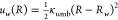 , where w was the window
index, the window centers ranged from R0 = 0.4 to R15 = 11.65 Å with a uniform
spacing of 0.75 Å, and the force constant was κumb = 6 kcal/mol. The initial structures for each window were obtained
by extracting appropriate frames from an NVT simulation
at 370 K during which folding occurred, using the same atomic system
as in the previous section (“Folding Thermodynamics of the
Chosen Peptide”). The system had been previously equilibrated
at 370 K and 1.01325 bar (NpT), giving a system size
of 50.83 Å × 48.91 Å × 25.52 Å for all windows.
Each window was run for 1200 ns of simulated time, with exchanges
attempted between neighboring windows every 2500 steps (0.01 ns) and
alternating between two sets of neighbors. Average acceptance rates
ranged from 0.19 to 0.61. The PMF was calculated by the weighted histogram
analysis method (WHAM),70,71 discarding the first
5 ns of each window.
, where w was the window
index, the window centers ranged from R0 = 0.4 to R15 = 11.65 Å with a uniform
spacing of 0.75 Å, and the force constant was κumb = 6 kcal/mol. The initial structures for each window were obtained
by extracting appropriate frames from an NVT simulation
at 370 K during which folding occurred, using the same atomic system
as in the previous section (“Folding Thermodynamics of the
Chosen Peptide”). The system had been previously equilibrated
at 370 K and 1.01325 bar (NpT), giving a system size
of 50.83 Å × 48.91 Å × 25.52 Å for all windows.
Each window was run for 1200 ns of simulated time, with exchanges
attempted between neighboring windows every 2500 steps (0.01 ns) and
alternating between two sets of neighbors. Average acceptance rates
ranged from 0.19 to 0.61. The PMF was calculated by the weighted histogram
analysis method (WHAM),70,71 discarding the first
5 ns of each window.
A similar protocol was used to calculate the free energy of folding CHP1404 in solution; however, the folded structure was highly unstable in solution, so stronger umbrella sampling restraints were needed to sample low RMSD values. Hence, we performed three independent replica-exchange umbrella sampling simulations, first using the same set of 16 windows as above, then with a set of 20 windows with from R0 = 0.4 to R19 = 10.85 Å with a spacing of 0.55 Å and κumb = 10 kcal/mol, and finally with another set of 20 windows with from R0 = 0.3 to R19 = 3.15 Å with a spacing of 0.15 Å and κumb = 100 kcal/mol. The resulting PMF, shown Figure 7A (blue curve), was generated from the data of all 56 windows using WHAM. The above calculations were repeated for the scrambled-sequence control peptide scram1404 (Figure S5 of the SI).
Free Energy of Adsorption
The free energy of adsorption was calculated by a multistep approach similar to that used for protein–ligand binding.43−45 In this approach, a biased adsorption free energy was calculated in the presence of conformational and orientational restraints that facilitate convergence. The effect of these restraints was then determined in separate free energy calculations, and their contributions to the free energy are removed to yield an unbiased free energy. Given the simpler geometry of the problem of adsorption compared to protein–ligand binding, fewer steps were needed. The five-step process is detailed in Figure S5 of the SI, and the free energy contributions are given in Table 1. The restraints are applied along two variables: RMSD from a folded reference structure (R), which represents the conformation, and the scalar product between vectors orthogonal to the peptide and graphene (nz), which represents the orientation. As shown in Figure S5A, nz was defined as the z-component of the normalized cross product between backbone vectors of the peptide. These vectors are always well-defined and stable because the nz collective variable is only used when the peptide is conformationally restrained.
For Step 1, we calculated the free energy required to apply the conformational
restraint  , where R* =
0.62 Å was the center of the restraint, and κR = 100 kcal mol–1 Å–2 was the force constant of the restraint. The PMF as a function of
the RMSD for the peptide in solution, wRsol(R), had already been obtained as described in the
previous section (“Free Energy of Folding”). The contribution
of this restraint to the free energy was
, where R* =
0.62 Å was the center of the restraint, and κR = 100 kcal mol–1 Å–2 was the force constant of the restraint. The PMF as a function of
the RMSD for the peptide in solution, wRsol(R), had already been obtained as described in the
previous section (“Free Energy of Folding”). The contribution
of this restraint to the free energy was
| 4 |
For Step 2, we calculated the free
energy required to apply the
orientational restraint 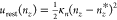 , where nz* = 1, and κn = 20000 kcal/mol. For an isotropic system,
like the free peptide in solution, the contribution of the nz restraint can be calculated
analytically. In this case, nz is uniformly distributed on its domain [ −1, 1], so wsol(nz) is a constant. The analog of eq 4 for nz becomes
, where nz* = 1, and κn = 20000 kcal/mol. For an isotropic system,
like the free peptide in solution, the contribution of the nz restraint can be calculated
analytically. In this case, nz is uniformly distributed on its domain [ −1, 1], so wsol(nz) is a constant. The analog of eq 4 for nz becomes
| 5 |
For Step 3, we calculated the PMF as a function of the z-component of the vector from the center of mass of the upper layer of graphene to the center of mass of the peptide, with the restraints urest(R) and urest(nz) applied (Figure 7B). The system used for this simulation was similar to that used in the “Free Energy of Folding” section except that it was somewhat larger along the z-axis (37.3 Å) to allow for desorption of the peptide. The free energy along z was calculated using the extended adaptive biasing force (eABF) algorithm72,73 as implemented in the Colvars module. The eABF grid was on the domain [3.2, 15.0] Å with a spacing of 0.05 Å.
For Step 4, we calculated the free energy contribution of releasing the nz restraints for the peptide at the graphite–water interface (while the conformational restraints were still applied). The eABF grid on nz extended from 0.6 to 1.0 with a spacing of 0.005. The PMF is shown in Figure S5. The contribution to the free energy was calculated by
| 6 |
For Step 5, we used the PMF as a function of RMSD for the peptide at the graphite–water interface, calculated as described in the “Free Energy of Folding” section. The contribution to the free energy ΔGreleaseconform was calculated by an analog to eq 6.
Free Energy of Assembly
Free energy of pair formation was calculated in a fashion similar to the adsorption free energy. We applied the same conformational restraints as above, for which the restraint free energy had already been obtained (+0.62 ± 0.04 per peptide). Additional restraints were applied to align each peptide along the y-axis, using a SpinAngle collective variable as implemented in the Colvars module,74 with centers of 0.0 and force constants of 0.5 kcal/mol. Calculation of the PMF along this variable is described in the section “Alignment with Respect to the Graphite Lattice” below. With conformational and alignment restraints applied to both peptides, we performed a two-dimensional eABF calculation, where the two collective variables were the x- and y-components of the displacement between the centers of mass of the two peptides. The eABF grid had a spacing of 0.1 Å along both directions on the domain x ∈ [8.8, 16.0] Å and y ∈ [ −14, 14] Å. For expediency, the free energy to release the restraints was calculated in two steps. First, both conformational restraints and one of the two alignment restraints were released over 400 ns, with the free energy estimated from the accumulated work as the force constants of these restraints were simultaneously reduced to zero.74 We demonstrated that 400 ns was sufficient time for the work to be quasi-reversible by repeating the calculation and performing similar forward and reverse calculations in 100 ns. All of these calculations yielded ΔGrelease in the range from −2.5 to −2.2 kcal/mol. Finally, the contribution of the remaining alignment restraint was computed by calculating the PMF along the SpinAngle coordinate for a single peptide of the bonded pair. The free energy values are summarized in Table 2.
Folding Dynamics after Adsorption from Solution
To prevent the peptides from desorbing, crossing the periodic boundary, and adsorbing to the lower graphene sheet, flat-bottom harmonic restraints were applied (using the Colvars module74) when the center of mass of the peptide exceeded a distance of 20 Å from the upper graphene sheet. This orientation of the peptide was quantified by calculating the vector product of vectors between consecutive residues
| 7 |
where n = 22 is the number of residues in the cyclic peptide, riCA is the position of the Cα atom of residue i, r–1 ≡ r22CA and r23 ≡ r1CA respecting the cyclic nature of the peptide, and ẑ is the direction orthogonal to the graphene sheet.
Self-Assembly of Chosen Peptide
Nine peptide molecules (cyc(GTGSGTGGPGGGCGTGTGSGPG)) in the folded conformation were placed atop two graphene sheets of dimensions 152.5 Å × 146.7 Å in a uniform 3 × 3 array. Water and Na+ and Cl– ions (≈150 mmol/L) were added to obtain an equilibrium z-dimension of 25.4 Å. At each of two temperatures (295 and 370 K), two replicates with slightly initial conditions were run.
Alignment with Respect to the Graphite Lattice
A free-energy calculation was performed for the peptide cyc(GTGSGTGGPGGGCGTGTGSGPG) to determine its tendency to align with the underlying graphene lattice. The calculation was performed with the eABF72,73 along a SpinAngle coordinate. The reference structure for this variable was chosen from a previous simulation where the long axis of the hairpin was closely aligned with a zigzag direction of the graphene sheet. We performed this free energy calculation in two replicates of 3000 ns each. The uncertainty in the free energy was estimated by integrating over the difference in the gradients between the two independent runs.22
Atomic Force Microscopy
The cyclic peptide CHP1404 and the scrambled-sequence control (also head-to-tail cyclized) were synthesized by a commercial service (LifeTein, LLC., Hillsborough, New Jersey, USA). In situ AFM experiments were performed on freshly cleaved highly oriented pyrolytic graphite (HOPG) with a Nanoscope V MultiMode scanning probe microscope (Veeco, Santa Barbara, CA) equipped with a closed-loop “vertical engage” J-scanner and a sealable tapping fluid cell. Images were acquired using rectangular-shaped silicon nitride cantilevers (Vista Probes, Phoenix, AZ) with spring constants of ≈0.1 N/m. Scan rates were set at 1–2 Hz with cantilever drive frequencies ranging from ≈7 to 9 kHz. The free amplitude of the cantilever was ≈20 nm, and the tapping amplitude was set at 75% of free amplitude. Peptide samples were prepared in 18 MΩ water, bath sonicated for 15 min, and directly injected into the fluid cell. After experimenting with different peptide concentrations, the peptide concentration used to produce the images in Figure 12 was 0.6 mg/mL (0.37 mmol/L).
Data and Software Availability
The simulation data described in this work are freely available for download from Zenodo (https://doi.org/10.5281/zenodo.6426152). The archive includes all files needed to run the simulations described here using NAMD, as well as the output of the simulations and analysis scripts. The files are organized into directories corresponding to the figures of the main text and Supporting Information. They include molecular model structure files (in CHARMM/NAMD psf or Amber prmtop format), force field parameter files (in CHARMM format), initial atomic coordinates (pdb format), NAMD configuration files, Colvars configuration files, NAMD log files, and NAMD output including restart files (in binary NAMD format) and trajectories in dcd format (downsampled to 10 ns per frame). Analysis is controlled by shell scripts (Bash-compatible) that call VMD Tcl scripts or Python scripts. These scripts and their output are also included.
Acknowledgments
This material is based upon work supported by the US National Science Foundation under grant no. DMR-1945589. The majority of the computing for this project was performed on the Beocat Research Cluster at Kansas State University, which is funded in part by NSF grants CHE-1726332, CNS-1006860, EPS-1006860, and EPS-0919443. This work used the Extreme Science and Engineering Discovery Environment (XSEDE) (allocation BIO200030), which is supported by the National Science Foundation grant number ACI-1548562.
Supporting Information Available
The Supporting Information is available free of charge at https://pubs.acs.org/doi/10.1021/acs.jcim.2c00419.
Results of additional simulations, sampling analysis for replica-exchange calculations, and circular dichroism spectra (PDF)
The authors declare no competing financial interest.
Supplementary Material
References
- Lou S.; Wang X.; Yu Z.; Shi L. Peptide Tectonics: Encoded Structural Complementarity Dictates Programmable Self-Assembly. Adv. Sci. 2019, 6, 1802043. 10.1002/advs.201802043. [DOI] [PMC free article] [PubMed] [Google Scholar]
- King N. P.; Sheffler W.; Sawaya M. R.; Vollmar B. S.; Sumida J. P.; André I.; Gonen T.; Yeates T. O.; Baker D. Computational Design of Self-assembling Protein Nanomaterials with Atomic Level Accuracy. Science 2012, 336, 1171–1174. 10.1126/science.1219364. [DOI] [PMC free article] [PubMed] [Google Scholar]
- Ljubetič A.; Lapenta F.; Gradišar H.; Drobnak I.; Aupič J.; Strmšek Ž.; Lainšček D.; Hafner-Bratkovič I.; Majerle A.; Krivec N.; Benčina1 M.; Pisanski T.; Ćirković Veličković T.; Round A.; Carazo J. M.; Melero R.; Jerala R. Design of Coiled-coil Protein-origami Cages That Self-assemble in Vitro and in Vivo. Nat. Biotechnol. 2017, 35, 1094. 10.1038/nbt.3994. [DOI] [PubMed] [Google Scholar]
- Bowerman C. J.; Nilsson B. L. Review Self-assembly of Amphipathic β-sheet Peptides: Insights and Applications. Peptide Science 2012, 98, 169–184. 10.1002/bip.22058. [DOI] [PubMed] [Google Scholar]
- Kotch F. W.; Raines R. T. Self-assembly of Synthetic Collagen Triple Helices. Proc. Natl. Acad. Sci. U.S.A. 2006, 103, 3028–3033. 10.1073/pnas.0508783103. [DOI] [PMC free article] [PubMed] [Google Scholar]
- Tanrikulu I. C.; Forticaux A.; Jin S.; Raines R. T. Peptide Tessellation Yields Micrometre-scale Collagen Triple Helices. Nature Chem. 2016, 8, 1008. 10.1038/nchem.2556. [DOI] [PMC free article] [PubMed] [Google Scholar]
- Knowles T. P.; Buehler M. J. Nanomechanics of Functional and Pathological Amyloid Materials. Nat. Nanotechnol. 2011, 6, 469–479. 10.1038/nnano.2011.102. [DOI] [PubMed] [Google Scholar]
- Knowles T. P.; Mezzenga R. Amyloid Fibrils as Building Blocks for Natural and Artificial Functional Materials. Adv. Mater. 2016, 28, 6546–6561. 10.1002/adma.201505961. [DOI] [PubMed] [Google Scholar]
- Li C.; Qin R.; Liu R.; Miao S.; Yang P. Functional Amyloid Materials at Surfaces/interfaces. Biomaterials Sci. 2018, 6, 462–472. 10.1039/C7BM01124E. [DOI] [PubMed] [Google Scholar]
- Gudlur S.; Sukthankar P.; Gao J.; Avila L. A.; Hiromasa Y.; Chen J.; Iwamoto T.; Tomich J. M. Peptide Nanovesicles Formed by the Self-assembly of Branched Amphiphilic Peptides. PLoS One 2012, 7, e45374 10.1371/journal.pone.0045374. [DOI] [PMC free article] [PubMed] [Google Scholar]
- Newcomb C. J.; Sur S.; Ortony J. H.; Lee O.-S.; Matson J. B.; Boekhoven J.; Yu J. M.; Schatz G. C.; Stupp S. I. Cell Death Versus Cell Survival Instructed by Supramolecular Cohesion of Nanostructures. Nature Comm 2014, 5, 3321. 10.1038/ncomms4321. [DOI] [PMC free article] [PubMed] [Google Scholar]
- Rodrigues de Almeida N.; Han Y.; Perez J.; Kirkpatrick S.; Wang Y.; Conda-Sheridan M. Design, Synthesis, and Nanostructure-dependent Antibacterial Activity of Cationic Peptide Amphiphiles. ACS Appl. Mater. Interfaces 2018, 11, 2790. 10.1021/acsami.8b17808. [DOI] [PMC free article] [PubMed] [Google Scholar]
- Zaldivar G.; Vemulapalli S.; Udumula V.; Conda-Sheridan M.; Tagliazucchi M. Self-Assembled Nanostructures of Peptide Amphiphiles: Charge Regulation by Size Regulation. J. Phys. Chem. C 2019, 123, 17606–17615. 10.1021/acs.jpcc.9b04280. [DOI] [Google Scholar]
- Mahmoudi M.; Akhavan O.; Ghavami M.; Rezaee F.; Ghiasi S. M. A. Graphene Oxide Strongly Inhibits Amyloid Beta Fibrillation. Nanoscale 2012, 4, 7322–7325. 10.1039/c2nr31657a. [DOI] [PubMed] [Google Scholar]
- Li P.; Chen X.; Yang W. Graphene-induced Self-assembly of Peptides into Macroscopic-scale Organized Nanowire Arrays for Electrochemical NADH Sensing. Langmuir 2013, 29, 8629–8635. 10.1021/la401881a. [DOI] [PubMed] [Google Scholar]
- Li Q.; Liu L.; Zhang S.; Xu M.; Wang X.; Wang C.; Besenbacher F.; Dong M. Modulating Aβ33–42 Peptide Assembly by Graphene Oxide. Chem.—Eur. J. 2014, 20, 7236–7240. 10.1002/chem.201402022. [DOI] [PubMed] [Google Scholar]
- Baweja L.; Balamurugan K.; Subramanian V.; Dhawan A. Effect of Graphene Oxide on the Conformational Transitions of Amyloid Beta Peptide: A Molecular Dynamics Simulation Study. J. Mol. Graph. Model. 2015, 61, 175–185. 10.1016/j.jmgm.2015.07.007. [DOI] [PubMed] [Google Scholar]
- Li M.; Zhao A.; Dong K.; Li W.; Ren J.; Qu X. Chemically Exfoliated WS2 Nanosheets Efficiently Inhibit Amyloid β-peptide Aggregation and Can Be Used for Photothermal Treatment of Alzheimer’s Disease. Nano Research 2015, 8, 3216–3227. 10.1007/s12274-015-0821-z. [DOI] [Google Scholar]
- Abb S.; Harnau L.; Gutzler R.; Rauschenbach S.; Kern K. Two-dimensional Honeycomb Network through Sequence-controlled Self-assembly of Oligopeptides. Nature Comm 2016, 7, 10335. 10.1038/ncomms10335. [DOI] [PMC free article] [PubMed] [Google Scholar]
- Chen Y.; Deng K.; Lei S.; Yang R.; Li T.; Gu Y.; Yang Y.; Qiu X.; Wang C. Single-molecule Insights into Surface-mediated Homochirality in Hierarchical Peptide Assembly. Nature Comm 2018, 9, 2711. 10.1038/s41467-018-05218-0. [DOI] [PMC free article] [PubMed] [Google Scholar]
- Xuan S.; Jiang X.; Spencer R. K.; Li N. K.; Prendergast D.; Balsara N. P.; Zuckermann R. N. Atomic-level Engineering and Imaging of Polypeptoid Crystal Lattices. Proc. Natl. Acad. Sci. U.S.A. 2019, 116, 22491–22499. 10.1073/pnas.1909992116. [DOI] [PMC free article] [PubMed] [Google Scholar]
- Poblete H.; Miranda-Carvajal I.; Comer J. Determinants of Alanine Dipeptide Conformational Equilibria on Graphene and Hydroxylated Derivatives. J. Phys. Chem. B 2017, 121, 3895–3907. 10.1021/acs.jpcb.7b01130. [DOI] [PubMed] [Google Scholar]
- Parchanšký V.; Kapitán J.; Kaminský J.; Šebestík J.; Bouř P. Ramachandran Plot for Alanine Dipeptide as Determined from Raman Optical Activity. J. Phys. Chem. Lett. 2013, 4, 2763–2768. 10.1021/jz401366j. [DOI] [PubMed] [Google Scholar]
- Mironov V.; Alexeev Y.; Mulligan V. K.; Fedorov D. G. A Systematic Study of Minima in Alanine Dipeptide. J. Comput. Chem. 2019, 40, 297–309. 10.1002/jcc.25589. [DOI] [PubMed] [Google Scholar]
- Imai Y. N.; Inoue Y.; Nakanishi I.; Kitaura K. Amide−π Interactions between Formamide and Benzene. J. Comput. Chem. 2009, 30, 2267–2276. 10.1002/jcc.21212. [DOI] [PubMed] [Google Scholar]
- Hughes Z. E.; Walsh T. R. What Makes a Good Graphene-binding Peptide? Adsorption of Amino Acids and Peptides at Aqueous Graphene Interfaces. J. Mater. Chem. B 2015, 3, 3211–3221. 10.1039/C5TB00004A. [DOI] [PubMed] [Google Scholar]
- Dasetty S.; Barrows J. K.; Sarupria S. Adsorption of Amino Acids on Graphene: Assessment of Current Force Fields. Soft Matter 2019, 15, 2359–2372. 10.1039/C8SM02621A. [DOI] [PubMed] [Google Scholar]
- Kumar K.; Woo S. M.; Siu T.; Cortopassi W. A.; Duarte F.; Paton R. S. Cation−π Interactions in Protein–ligand Binding: Theory and Data-mining Reveal Different Roles for Lysine and Arginine. Chem. Sci. 2018, 9, 2655–2665. 10.1039/C7SC04905F. [DOI] [PMC free article] [PubMed] [Google Scholar]
- Sugita Y.; Okamoto Y. Replica-exchange Molecular Dynamics Method for Protein Folding. Chem. Phys. Lett. 1999, 314, 141–151. 10.1016/S0009-2614(99)01123-9. [DOI] [Google Scholar]
- Fossey S. A.; Némethy G.; Gibson K. D.; Scheraga H. A. Conformational Energy Studies of β-sheets of Model Silk Fibroin Peptides. I. Sheets of Poly (Ala-Gly) Chains. Biopolymers 1991, 31, 1529–1541. 10.1002/bip.360311309. [DOI] [PubMed] [Google Scholar]
- Kuhlman B.; Dantas G.; Ireton G. C.; Varani G.; Stoddard B. L.; Baker D. Design of a Novel Globular Protein Fold with Atomic-level Accuracy. Science 2003, 302, 1364–1368. 10.1126/science.1089427. [DOI] [PubMed] [Google Scholar]
- Blandl T.; Cochran A. G.; Skelton N. J. Turn Stability in β-hairpin Peptides: Investigation of Peptides Containing 3:5 Type I G1 Bulge Turns. Protein Sci. 2003, 12, 237–247. 10.1110/ps.0228603. [DOI] [PMC free article] [PubMed] [Google Scholar]
- Russell S. J.; Blandl T.; Skelton N. J.; Cochran A. G. Stability of Cyclic β-hairpins: Asymmetric Contributions from Side Chains of a Hydrogen-bonded Cross-strand Residue Pair. J. Am. Chem. Soc. 2003, 125, 388–395. 10.1021/ja028075l. [DOI] [PubMed] [Google Scholar]
- Cochran A. G.; Tong R. T.; Starovasnik M. A.; Park E. J.; McDowell R. S.; Theaker J.; Skelton N. J. A Minimal Peptide Scaffold for β-turn Display: Optimizing a Strand Position in Disulfide-cyclized β-hairpins. J. Am. Chem. Soc. 2001, 123, 625–632. 10.1021/ja003369x. [DOI] [PubMed] [Google Scholar]
- Abraham M. J.; Murtola T.; Schulz R.; Páll S.; Smith J. C.; Hess B.; Lindahl E. GROMACS: High Performance Molecular Simulations through Multi-level Parallelism from Laptops to Supercomputers. SoftwareX 2015, 1, 19–25. 10.1016/j.softx.2015.06.001. [DOI] [Google Scholar]
- Tanner D. E.; Chan K.-Y.; Phillips J. C.; Schulten K. Parallel Generalized Born Implicit Solvent Calculations with NAMD. J. Chem. Theory Comput. 2011, 7, 3635–3642. 10.1021/ct200563j. [DOI] [PMC free article] [PubMed] [Google Scholar]
- Onufriev A.; Bashford D.; Case D. A. Exploring Protein Native States and Large-scale Conformational Changes with a Modified Generalized Born Model. Proteins: Struct., Funct., Bioinf. 2004, 55, 383–394. 10.1002/prot.20033. [DOI] [PubMed] [Google Scholar]
- Huang J.; Rauscher S.; Nawrocki G.; Ran T.; Feig M.; de Groot B.; Grubmüller H.; MacKerell A. Jr CHARMM36m: an Improved Force Field for Folded and Intrinsically Disordered Proteins. Nature Meth 2017, 14, 71–73. 10.1038/nmeth.4067. [DOI] [PMC free article] [PubMed] [Google Scholar]
- Maier J. A.; Martinez C.; Kasavajhala K.; Wickstrom L.; Hauser K. E.; Simmerling C. ff14SB: Improving the Accuracy of Protein Side Chain and Backbone Parameters from ff99SB. J. Chem. Theory Comput. 2015, 11, 3696–3713. 10.1021/acs.jctc.5b00255. [DOI] [PMC free article] [PubMed] [Google Scholar]
- Hummer G.; Rasaiah J. C.; Noworyta J. P. Water Conduction through the Hydrophobic Channel of a Carbon Nanotube. Nature 2001, 414, 188–190. 10.1038/35102535. [DOI] [PubMed] [Google Scholar]
- Comer J.; Chen R.; Poblete H.; Vergara-Jaque A.; Riviere J. E. Predicting Adsorption Affinities of Small Molecules on Carbon Nanotubes Using Molecular Dynamics Simulation. ACS Nano 2015, 9, 11761–11774. 10.1021/acsnano.5b03592. [DOI] [PubMed] [Google Scholar]
- Azhagiya Singam E. R.; Zhang Y.; Magnin G.; Miranda-Carvajal I.; Coates L.; Thakkar R.; Poblete H.; Comer J. Thermodynamics of Adsorption to Graphenic Surfaces from Aqueous Solution. J. Chem. Theory Comput. 2019, 15, 1302–1316. 10.1021/acs.jctc.8b00830. [DOI] [PubMed] [Google Scholar]
- Woo H.-J.; Roux B. Calculation of Absolute Protein–ligand Binding Free Energy from Computer Simulations. Proc. Natl. Acad. Sci. U.S.A. 2005, 102, 6825–6830. 10.1073/pnas.0409005102. [DOI] [PMC free article] [PubMed] [Google Scholar]
- Gumbart J. C.; Roux B.; Chipot C. Standard Binding Free Energies from Computer Simulations: What Is the Best Strategy?. J. Chem. Theory Comput. 2013, 9, 794–802. 10.1021/ct3008099. [DOI] [PMC free article] [PubMed] [Google Scholar]
- Fu H.; Cai W.; Hénin J.; Roux B.; Chipot C. New Coarse Variables for the Accurate Determination of Standard Binding Free Energies. J. Chem. Theory Comput. 2017, 13, 5173–5178. 10.1021/acs.jctc.7b00791. [DOI] [PubMed] [Google Scholar]
- Melis C.; Bussi G.; Lummis S. C.; Molteni C. Trans-cis Switching Mechanisms in Proline Analogues and Their Relevance for the Gating of the 5-HT3 Receptor. J. Phys. Chem. B 2009, 113, 12148–12153. 10.1021/jp9046962. [DOI] [PMC free article] [PubMed] [Google Scholar]
- Thakkar R.; Gajaweera S.; Comer J. Organic Contaminants and Atmospheric Nitrogen at the Graphene–water Interface: A Simulation Study. Nanoscale Adv. 2022, 4, 1741–1757. 10.1039/D1NA00570G. [DOI] [PMC free article] [PubMed] [Google Scholar]
- Uhlig M. R.; Benaglia S.; Thakkar R.; Comer J.; Garcia R. Atomically Resolved Interfacial Water Structures on Crystalline Hydrophilic and Hydrophobic Surfaces. Nanoscale 2021, 13, 5275–5283. 10.1039/D1NR00351H. [DOI] [PubMed] [Google Scholar]
- Phillips J. C.; Braun R.; Wang W.; Gumbart J.; Tajkhorshid E.; Villa E.; Chipot C.; Skeel R. D.; Kale L.; Schulten K. Scalable Molecular Dynamics with NAMD. J. Comput. Chem. 2005, 26, 1781–1802. 10.1002/jcc.20289. [DOI] [PMC free article] [PubMed] [Google Scholar]
- Hopkins C. W.; Le Grand S.; Walker R. C.; Roitberg A. E. Long-time-step Molecular Dynamics through Hydrogen Mass Repartitioning. J. Chem. Theory Comput. 2015, 11, 1864–1874. 10.1021/ct5010406. [DOI] [PubMed] [Google Scholar]
- Miyamoto S.; Kollman P. A. SETTLE: an Analytical Version of the SHAKE and RATTLE Algorithm for Rigid Water Models. J. Comput. Chem. 1992, 13, 952–962. 10.1002/jcc.540130805. [DOI] [Google Scholar]
- Andersen H. C. RATTLE: A “Velocity” Version of the SHAKE Algorithm for Molecular Dynamics Calculations. J. Chem. Phys. 1983, 52, 24–34. 10.1016/0021-9991(83)90014-1. [DOI] [Google Scholar]
- Darden T. A.; York D. M.; Pedersen L. G. Particle Mesh Ewald: An N log N Method for Ewald Sums in Large Systems. J. Chem. Phys. 1993, 98, 10089–10092. 10.1063/1.464397. [DOI] [Google Scholar]
- Humphrey W.; Dalke A.; Schulten K. VMD – Visual Molecular Dynamics. J. Mol. Graphics 1996, 14, 33–38. 10.1016/0263-7855(96)00018-5. [DOI] [PubMed] [Google Scholar]
- Kohlmeyer A.; Vermaas J.. TopoTools, Release 1.7; 2017. https://zenodo.org/record/545655#.YtsYZ7bMKUk (accessed 2022-07-22)
- Phillips J. C.; Hardy D. J.; Maia J. D.; Stone J. E.; Ribeiro J. V.; Bernardi R. C.; Buch R.; Fiorin G.; Hénin J.; Jiang W.; McGreevy R.; Melo M. C. R.; Radak B. K.; Skeel R. D.; Singharoy A.; Wang Y.; Roux B.; Aksimentiev A.; Luthey-Schulten Z.; Kalé L. V.; Schulten K.; Chipot C.; Tajkhorshid E. Scalable Molecular Dynamics on CPU and GPU Architectures with NAMD. J. Chem. Phys. 2020, 153, 044130. 10.1063/5.0014475. [DOI] [PMC free article] [PubMed] [Google Scholar]
- Towns J.; Cockerill T.; Dahan M.; Foster I.; Gaither K.; Grimshaw A.; Hazlewood V.; Lathrop S.; Lifka D.; Peterson G. D.; Scott J. R.; Wilkens-Diehr N. XSEDE: Accelerating Scientific Discovery. Comput. Sci. Eng. 2014, 16, 62–74. 10.1109/MCSE.2014.80. [DOI] [Google Scholar]
- Feller S. E.; Zhang Y. H.; Pastor R. W.; Brooks B. R. Constant Pressure Molecular Dynamics Simulations — The Langevin Piston Method. J. Chem. Phys. 1995, 103, 4613–4621. 10.1063/1.470648. [DOI] [Google Scholar]
- MacKerell A. D. Jr.; Bashford D.; Bellott M.; Dunbrack R. L. Jr.; Evanseck J. D.; Field M. J.; Fischer S.; Gao J.; Guo H.; Ha S.; Joseph-McCarthy D.; Kuchnir L.; Kuczera K.; Lau F. T. K.; Mattos C.; Michnick S.; Ngo T.; Nguyen D. T.; Prodhom B.; Reiher W. E. III; Roux B.; Schlenkrich M.; Smith J. C.; Stote R.; Straub J.; Watanabe M.; Wiórkiewicz-Kuczera J.; Yin D.; Karplus M. All–atom Empirical Potential for Molecular Modeling and Dynamics Studies of Proteins. J. Phys. Chem. B 1998, 102, 3586–3616. 10.1021/jp973084f. [DOI] [PubMed] [Google Scholar]
- MacKerell A. Jr; Feig M.; Brooks C. III Improved Treatment of the Protein Backbone in Empirical Force Fields. J. Am. Chem. Soc. 2004, 126, 698–699. 10.1021/ja036959e. [DOI] [PubMed] [Google Scholar]
- Best R. B.; Zhu X.; Shim J.; Lopes P. E.; Mittal J.; Feig M.; MacKerell A. D. Jr Optimization of the Additive CHARMM All-atom Protein Force Field Targeting Improved Sampling of the Backbone ϕ, ψ and Side-chain χ1 and χ2 Dihedral Angles. J. Chem. Theory Comput. 2012, 8, 3257–3273. 10.1021/ct300400x. [DOI] [PMC free article] [PubMed] [Google Scholar]
- Vanommeslaeghe K.; Hatcher E.; Acharya C.; Kundu S.; Zhong S.; Shim J.; Darian E.; Guvench O.; Lopes P.; Vorobyov I.; MacKerell A. D. CHARMM General Force Field: A Force Field for Drug-like Molecules Compatible with the CHARMM All-atom Additive Biological Force Fields. J. Comput. Chem. 2010, 31, 671–690. 10.1002/jcc.21367. [DOI] [PMC free article] [PubMed] [Google Scholar]
- Jorgensen W. L.; Chandrasekhar J.; Madura J. D.; Impey R. W.; Klein M. L. Comparison of Simple Potential Functions for Simulating Liquid Water. J. Chem. Phys. 1983, 79, 926–935. 10.1063/1.445869. [DOI] [Google Scholar]
- Case D.; Aktulga H.; Belfon K.; Ben-Shalom I.; Brozell S.; Cerutti D.; T C. III; Cisneros G.; Cruzeiro V.; Darden T.; Duke R.; Giambasu G.; Gilson M.; Gohlke H.; Goetz A.; Harris R.; Izadi S.; Izmailov S.; Jin C.; Kasavajhala K.; Kaymak M.; King E.; Kovalenko A.; Kurtzman T.; Lee T.; LeGrand S.; Li P.; Lin C.; Liu J.; Luchko T.; Luo R.; Machado M.; Man V.; Manathunga M.; Merz K.; Miao Y.; Mikhailovskii O.; Monard G.; Nguyen H.; O’Hearn K.; Onufriev A.; Pan F.; Pantano S.; Qi R.; Rahnamoun A.; Roe D.; Roitberg A.; Sagui C.; Schott-Verdugo S.; Shen J.; Simmerling C.; Skrynnikov N.; Smith J.; Swails J.; Walker R.; Wang J.; Wei H.; Wolf R.; Wu X.; Xue Y.; York D.; Zhao S.; Kollman P.. Amber 2021; University of California: San Francisco, 2021.
- Swails J.; Hernandez C.; Mobley D. L.; Nguyen H.; Wang L.-P.; Janowski P.. ParmEd; 2010. https://github.com/ParmEd/ParmEd (accessed 2022-07-22).
- Faraldo-Gómez J. D.; Roux B. Characterization of Conformational Equilibria through Hamiltonian and Temperature Replica-exchange Simulations: Assessing Entropic and Environmental Effects. J. Comput. Chem. 2007, 28, 1634–1647. 10.1002/jcc.20652. [DOI] [PubMed] [Google Scholar]
- Jo S.; Jiang W. A Generic Implementation of Replica Exchange with Solute Tempering (REST2) Algorithm in NAMD for Complex Biophysical Simulations. Comput. Phys. Commun. 2015, 197, 304–311. 10.1016/j.cpc.2015.08.030. [DOI] [Google Scholar]
- Chaudhury S.; Lyskov S.; Gray J. J. PyRosetta: a Script-based Interface for Implementing Molecular Modeling Algorithms Using Rosetta. Bioinformatics 2010, 26, 689–691. 10.1093/bioinformatics/btq007. [DOI] [PMC free article] [PubMed] [Google Scholar]
- Murata K.; Sugita Y.; Okamoto Y. Free Energy Calculations for DNA Base Stacking by Replica-exchange Umbrella Sampling. Chem. Phys. Lett. 2004, 385, 1–7. 10.1016/j.cplett.2003.10.159. [DOI] [Google Scholar]
- Kumar S.; Rosenberg J. M.; Bouzida D.; Swendsen R. H.; Kollman P. A. The Weighted Histogram Analysis Method for Free-energy Calculations on Biomolecules. I. The Method. J. Comput. Chem. 1992, 13, 1011–1021. 10.1002/jcc.540130812. [DOI] [Google Scholar]
- Roux B. The Calculation of the Potential of Mean Force Using Computer Simulations. Comput. Phys. Commun. 1995, 91, 275–282. 10.1016/0010-4655(95)00053-I. [DOI] [Google Scholar]
- Comer J.; Gumbart J. C.; Hénin J.; Lelièvre T.; Pohorille A.; Chipot C. The Adaptive Biasing Force Method: Everything You Always Wanted to Know But Were Afraid to Ask. J. Phys. Chem. B 2015, 119, 1129–1151. 10.1021/jp506633n. [DOI] [PMC free article] [PubMed] [Google Scholar]
- Fu H.; Shao X.; Chipot C.; Cai W. Extended Adaptive Biasing Force Algorithm. An on-the-fly Implementation for Accurate Free-energy Calculations. J. Chem. Theory Comput. 2016, 12, 3506–3513. 10.1021/acs.jctc.6b00447. [DOI] [PubMed] [Google Scholar]
- Fiorin G.; Klein M. L.; Hénin J. Using Collective Variables to Drive Molecular Dynamics Simulations. Math. Probl. Eng. 2013, 111, 3345–3362. 10.1080/00268976.2013.813594. [DOI] [Google Scholar]
Associated Data
This section collects any data citations, data availability statements, or supplementary materials included in this article.
Supplementary Materials
Data Availability Statement
The simulation data described in this work are freely available for download from Zenodo (https://doi.org/10.5281/zenodo.6426152). The archive includes all files needed to run the simulations described here using NAMD, as well as the output of the simulations and analysis scripts. The files are organized into directories corresponding to the figures of the main text and Supporting Information. They include molecular model structure files (in CHARMM/NAMD psf or Amber prmtop format), force field parameter files (in CHARMM format), initial atomic coordinates (pdb format), NAMD configuration files, Colvars configuration files, NAMD log files, and NAMD output including restart files (in binary NAMD format) and trajectories in dcd format (downsampled to 10 ns per frame). Analysis is controlled by shell scripts (Bash-compatible) that call VMD Tcl scripts or Python scripts. These scripts and their output are also included.