. 2018 Nov 15;1(2):728–734. doi: 10.1039/c8na00277k

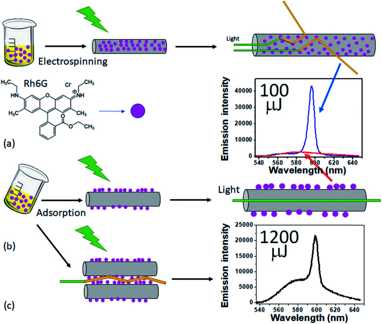
Fig. 7. Schematics of incorporating Rh6G, the gain medium of the studied RL, into the nanofiber matrix. (a) Conventional strategy: Rh6G solution is added to the polymeric mixture before performing electrospinning, leading to the molecules to be mainly inside the resulting nanofibers. The inset shows the RL emission spectrum for a pump energy of 100 μJ (blue line). (b) Drop-casting the Rh6G solution on the previously electrospun nanofibers, which causes the Rh6G molecules to be mainly adsorbed on the already existing nanofibers. The resulting emission spectrum for a pump energy of 100 μJ can also be seen in the inset of (a) (red line), which shows no RL action. (c) Sketch of the RL feedback mechanism in the case of the Rh6G molecules adsorbed on the surface of the nanofibers. The inset shows the resulting emission when the system is excited with 1200 μJ (more than 12× larger than the pump energy threshold), still showing some fluorescent background together with a RL emission peak. The results are for the sample CA + 10% PEO.

Fig. 7