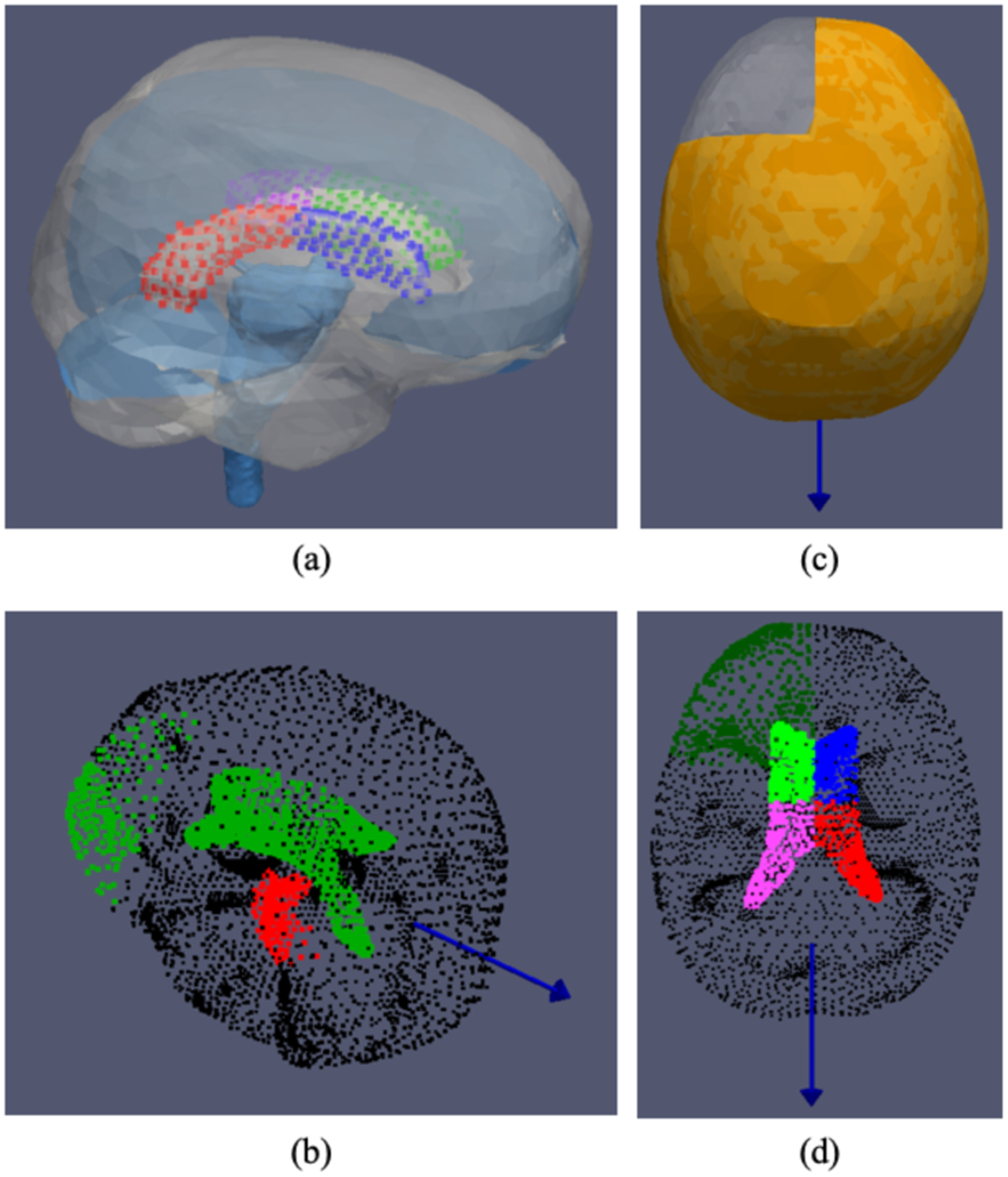
Fig. 2.

(a) Computational domain of the patient specific biomechanical model. Patient specific falx, tentorium and brain stem structures determined via an automated process using rigid and nonrigid image registration between patient imaging data and an atlas image. The lateral ventricle is further partitioned into four segments (illustrated with different colors) for additional boundary condition considerations. (b)-(d) An example of boundary conditions considered, where the blue vector represents the direction of gravity with the patient in supine position. (b) Displacement condition: green is stress free nodes, black is slip condition nodes, red or brain stem region is for fixed displacement. (c) Fluid condition: asymmetric drainage simulated in the model where orange represents the tissue submerged in CSF. (d) Pressure condition: dark green is Dirichlet reference pressure, black is no drainage condition and four segments of the ventricle (different colors of neon green, blue, pink and red) are given additional Dirichlet pressure considerations to simulate the effect of pneumocephalus.
