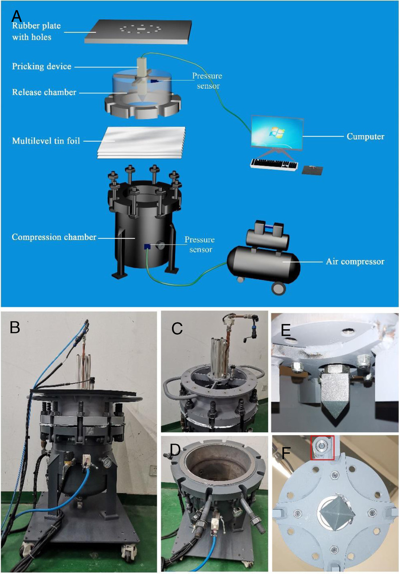
Figure 1.

The self-made mini shock tube simulation device. (A) Model diagram of the device. The device consists of five parts: compression chamber, release chamber, pricking device, pressure sensor and computer control system. Both the compress chamber and the release chamber are respectively vertical steel tubes and are separated by multilevel tin foils in the middle. The compression chamber is connected with an air compressor. The compressed air is injected into the compression chamber through the air compressor when the control system is turned on. When the pressure-setting value is reached, the pricking device pierces the aluminum film and produces instantaneous shock wave. The shock wave generated by the device ranges from 0 to 2 bar. (B–F) Photos of the device. (B) Shock tube main body. (C) Release chamber. (D) Compression chamber. (E) Pricking device. (F) Pressure sensor.
