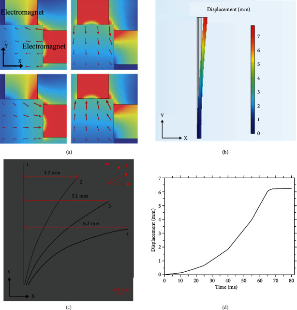
Figure 2.

Schematic diagram of the magnetic response tip of a soft microrobot. (a) Simulation of the magnetic field along the negative x-axis, negative y-axis, positive x-axis, and positive y-axis. (b) Simulation of the continuum microrobot bending. (c) The bending of the actual soft tip under the applied magnetic field. (d) The displacement response to the current of 4A.
