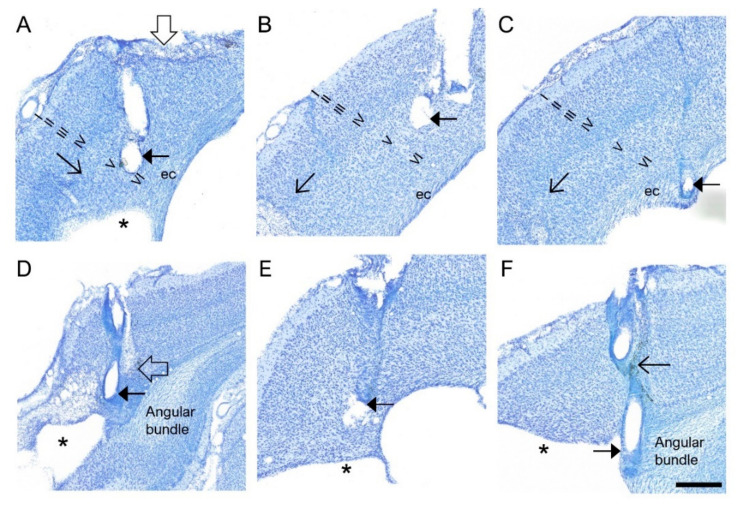
Figure 3.
(A–F) Electrode tracts. Histological images from the coronal thionine-stained sections of 6 rats, showing the tracts of the bipolar intracortical electrodes and location of the lower electrode tip (filled arrowhead). Roman numerals indicate the cortical layers. In panels (A,B) the electrode tip is located in layer V of the perilesional cortex. Note the electrode track-related lesion on the surface of the brain in panel (A) (open filled arrow). In panel (A), the electrode tip is within 500 µm from the edge of the TBI-induced lesion cavity (asterisk). In panel (C), the electrode tip is in the external capsule (ec). In panel (D) the electrode tip is within the cortical lesion, close to the angular bundle. Open arrow points to the electrode path associated neurodegeneration. In panel (E), the electrode tip is close to the edge of the lesion cavity (asterisk). In panel (F), the electrode tip is within the angular bundle (closed arrowhead). The open arrowhead points to the location of the upper electrode in layer IV (open arrow). The dark staining indicates iron deposits (arrowheads) adjacent to the electrode path. Scale bar = 500 µm.

