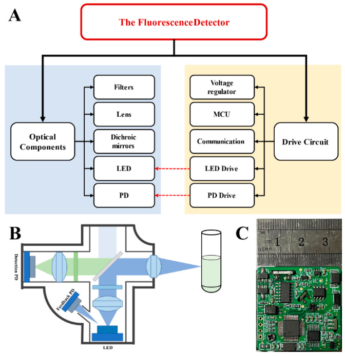
Figure 1.
Overall structure of the detector: (A) a functional block diagram of the fluorescence detector, including optical components and drive circuit; (B) a schematic diagram of the optical path—blue indicates the excitation light, and green indicates the fluorescence emitted by sample; (C) a printed circuit board (PCB) picture of the fluorescence detector.

