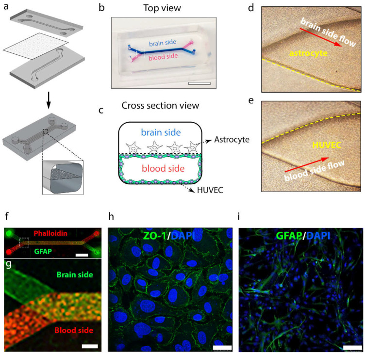
Figure 7.
Blood–brain barrier-on-a-chip model. (a) Design of PDMS microchip and schematic illustration of BBB chip. A porous membrane was sandwiched between two PDMS parts after treatment with oxygen plasma. (b) Top view of fabricated BBB chip filled with blue ink and red ink for brain side and blood side, respectively. Scale bar: 10 mm. (c) Schematic of cross-section view of BBB chip with co-cultured endothelial cell and astrocytes. (d) Enlarged brain-side image and (e) enlarged blood-side image of microchannel junction in the white square range of BBB chip of (b). (f) Immunocytochemistry image of co-cultured HUVECs with astrocytes in the whole BBB chip. (g) Enlarged fluorescence image of microchannel junction in the white square range in (f). (h) Immunofluorescence micrographs of the HUVECs cultured on-chip for 24 h, labeled with tight junction protein ZO-1. Scale bar: 25 µm. (i) Immunocytochemistry image of GRAP of astrocytes. Scale bar: 25 µm.

