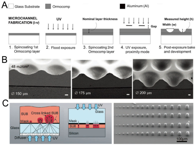
Figure 2.

Lithography in proximity mode or backside lithography for the fabrication of concave microwells. (A) UV exposure of polymer Ormocomp® in proximity mode: first, a thin layer of Ormocomp® was coated on a glass substrate; then, another Ormocompe® layer was coated and exposed to UV in proximity mode. After development, concave microwells were formed [38]. Reprinted (adapted) from [38]. Copyright (2017) with permission from AIP Publishing. (B) SEM pictures of concave microwells fabricated by the method described in (A) [39]. Scale bars: 20 µm. Reprinted (adapted) from [39] under the terms of the Creative Commons CC BY license. (C) The schematic view of SU-8 backside lithography: a glass diffuser was used, together with a glass mask, to diffuse the collimated UV light and crosslink dome-like SU-8 microstructures [40]. Reprinted (adapted) from [40]. Copyright (2019) with permission from the Royal Society of Chemistry.
