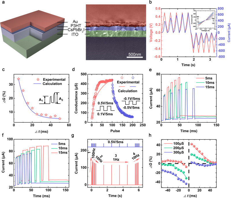
Fig. 2. Emulation of artificial synapses.
a The schematic and the cross-sectional SEM image of Au/P3HT/CsPbBr2I/ITO memristor. b The current with respect to DC voltage sweeps, the device conductance gradually increase (decrease) under positive (negative) sweeps of 0.5 V (−0.5 V). c The PPF ratio as a function of presynaptic pulse interval which can be expressed as . The pulse width and amplitude were set to 5 ms and 0.5 V. d The modulation of device conductance as a function of 100 consecutive potentiating and 100 depressing pulses. e Emulation of EPSC versus pulse interval at 5 ms, 10 ms and 15 ms. f Emulation of EPSC versus pulse width at 5 ms, 10 ms and 15 ms. g The device response to consecutive presynaptic pulse sequences at the frequencies of 100 Hz, 10 Hz, 1 Hz and 10 Hz. h The STDP learning rule simulated at three different initial states (G0 = 100 μs, 200 μs, 300 μs) as a function of presynaptic and postsynaptic pulses interval.

