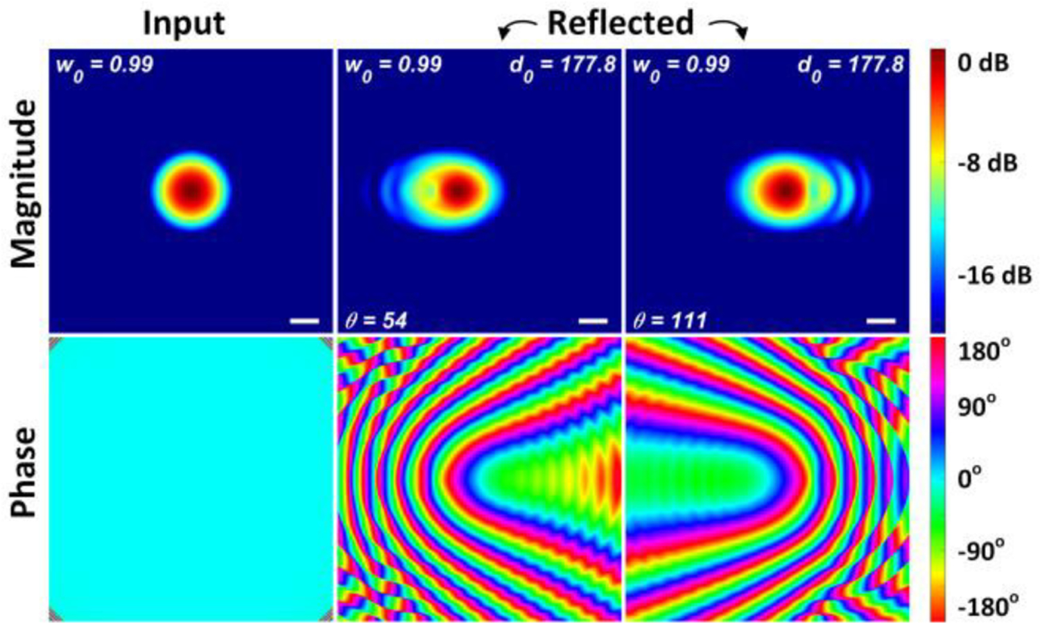
Figure A19.

Magnitude and phase at the detector plane. (Left column) an ideal TEM0,0 Gaussian beam waist is placed at the input plane. (Middle) the reflected beam magnitude and phase sampled at the input plane after routing through OAP mirrors A and B, reflection from the spherical target and then back through OAP A and B. The scan mirror directs the beam centroid at an angle of θ = 54° w.r.t. the z-axis and the OAP mirror tip separation is d0 = 177.8 mm. (Right) same as middle except θ = 111°
