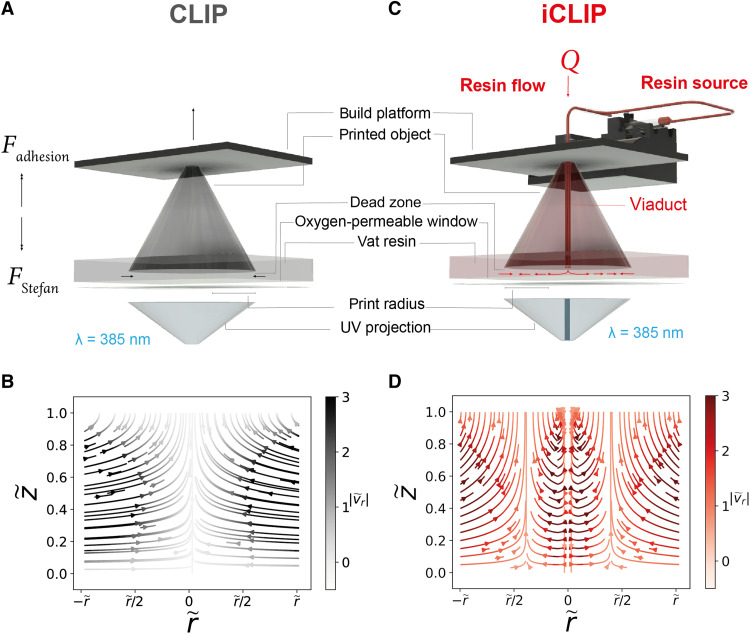
Fig. 1. Injection continuous liquid interface production.
(A) Traditional CLIP process, with force diagram for the printed object and resin flows indicated. (B) Analytically derived dead zone velocity fields and pressure gradients from the lubrication theory while printing a cylindrical geometry by CLIP, where and are the vertical and radial distances in the dead zone, respectively, and is the radial velocity. Darker hues indicate higher-magnitude velocity vectors, and, conversely, lighter hues indicate stagnation zones of low-fluid velocity. (C) iCLIP process indicating the flow of the injected resin from a pressurized source through microfluidic ducts engineered within the growing part into the dead zone. (D) Analytically derived dead zone velocity fields and pressure gradients from the lubrication theory while printing a cylindrical geometry by CLIP, with continuous injection through a central viaduct.

