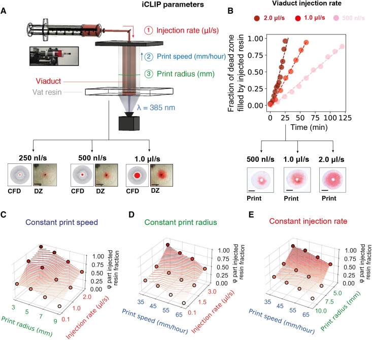
Fig. 4. Multimaterial iCLIP control strategy.
(A) Test geometry for calibrating injection rates during iCLIP, with control parameters that can be tuned during an iCLIP print to adjust the fraction of the vat to injected resin in a part. Below are images of the dead zone during prints with varying injection rates, with corresponding CFD simulation predictions. (B) Correlation between administered injection rate and the fraction of the part formed by injected resin, for three different injection profiles. (C to E) Parameter sweep experiments adjusting one of three control parameters during iCLIP to calibrate material fractions of vat to injected resin in a part. Scale bars, 1 cm. DZ, dead zone.

