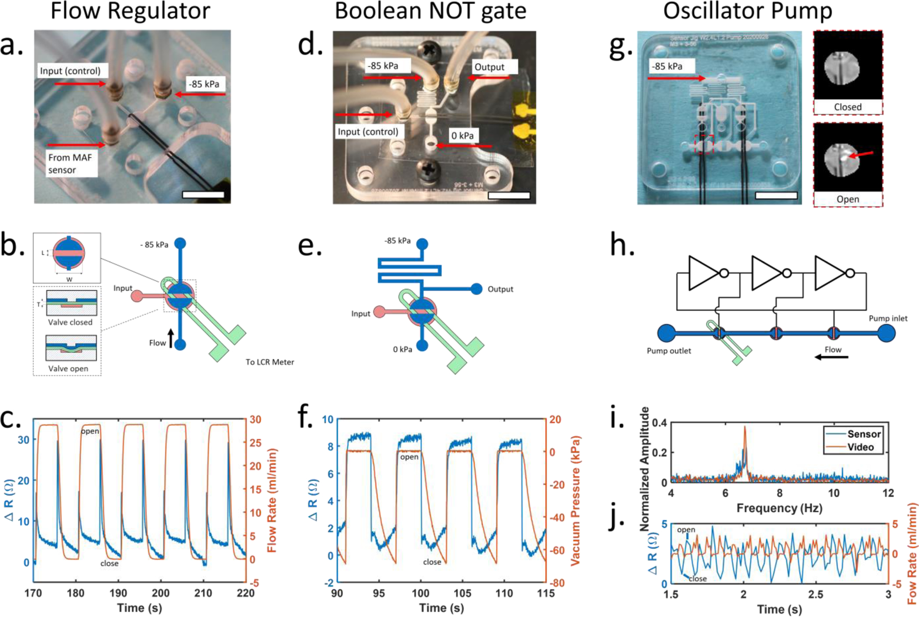
Fig. 3.

(a) Sensor integrated into an elastomeric membrane valve for control of reagent flow. White scale bar is 1 cm (b) Valve construction details. Close up view of overhead (top inset) and cross-section of valve (bottom inset). Channels on the control and flow layers are shown in red and blue, respectively. Sensor is embedded in the membrane shown in green. Valve seat length (L) = 1.2 mm, valve seat width (W) = 2.4 mm, membrane thickness (T) = 0.6 mm. (c) Sensor resistance increases when the valve is opened or closed. (d) Sensor integrated into a microfluidic inverter logic gate for microfluidic computing. (e) Inverter gate construction details. Channels on the control and flow layers are shown in red and blue, respectively. Sensor placement shown in green. (f) Comparison of sensor resistance and inverter output over time. (g) Photo of microfluidic oscillator pump with integrated sensor. Light reflected from a single valve was used for high speed video analysis (inset). Only the sensor on the left is used. (h) Schematic of peristaltic pump controlled by integrated ring oscillator circuit. The sensor was placed under the final pump valve to detect opening and closing. (i) A comparison of sensor data and high-speed video for monitoring oscillation frequency show matching peaks at 6.71 Hz. (j) Flow rate from the peristaltic pump measured using external hot wire anemometer and corresponding sensor measurements from the final valve in the pump. All scale bars are 1cm.
