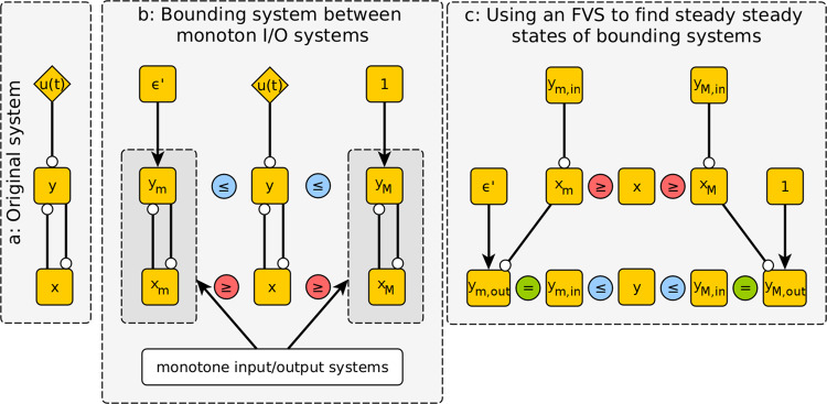
Fig. 2. Schematic of stable motif procedure applied to the system of Eq. 6.
The network structure of the system is depicted in panel a. Circle-tipped arrows represent inhibition, while wedge-tipped arrows represent activation. In panel b, the bounding systems in Eqs. 8 and 9 are depicted alongside the original system. Note that these bounding systems are monotone input/output systems. Panel c illustrates the characteristic feedback method of identifying steady states in monotone input/output systems, wherein the effect of overriding a feedback vertex set (FVS), in this case, the set containing or , is considered, as described in the example of Eq. 4.

