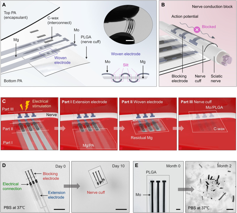
Fig. 1. Materials and designs for a bioresorbable electrical stimulator for nerve conduction block.
(A) Schematic illustration of a stimulator that consists of mechanically woven interconnects (Mg: 1 mm wide, 50 μm thick; Mo: 300 μm wide, 15 μm thick) to electrodes with a tripolar configuration mounted on a nerve cuff (PLGA, 40 μm thick). All active elements reside between a pair of bioresorbable polymer films (PA, 400 μm thick) except the region of the cuff where exposed electrodes deliver electrical stimulation to the nerve. Top inset: Image of a flexible device bent with the fingertips. Bottom inset: Detailed cross-sectional view of the woven electrode. Scale bar, 10 mm (top inset). (B) Schematic illustration of the process of nerve conduction block induced by a bioresorbable electrical stimulator in a cuff geometry. Mo electrodes that wrap around the nerve deliver electrical stimulation to block the conduction of action potential. (C) Illustration of the use, release, and bioresorption of the device through various stages of its lifetime. Sequential processes of dissolution engineered by choices in component designs and materials determine the functional and physical lifetimes. A series of images show the process of dissolution of a device during immersion in 1× PBS (pH 7.4) at physiological temperatures (37°C). (D) Day 10: Dissolution of the extension electrodes (Mg/PA). Scale bars, 5 mm. (E) Month 2: Disintegration and dissolution of the nerve cuff (Mo/PLGA). Scale bars, 1 mm.

