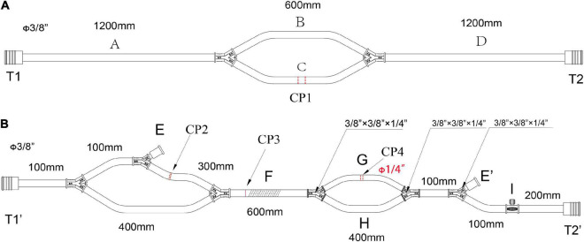
FIGURE 1.
The main pipelines for cannulation and functional consumables connection in the LHB circuit. (A) The pipelines for cannulation, all diameters of the circuits are 3/8 inch, CP1 is the cut-point for connection of the cannulation of the inferior left pulmonary vein and the aortic cannulation. (B) The functional consumables connection pipelines of the LHB circuit. CP2 is the cut-point for the connection of a hard-shell reservoir, CP3 is the cut-point for a centrifugal pump, and CP4 for the heat exchanger. Line F can be occluded by a roller pump rather than a centrifugal pump in CP3. The port E and port E’ are a pair for an ultrafilter. Port I with a side hole is connected with a T-type adapter, which can be connected to a pressure monitor, and an arterial sampling connector. Both the port T1 in panel (A) and the port T1’ in panel (B) are connected with an oxygen saturation monitor or a connector. The port T2 in panel (A) and the port T2’ in panel (B) were connected with a Y-type connector (φ3/8” x3/8” x1/4”), and the 1/4-inch port of the connector is linked to the line for the selective visceral perfusion.

