Figure 1.
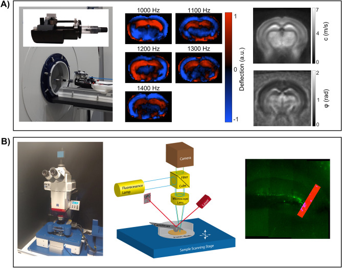
MRE and AFM setup. (A) On the left, the 7-Tesla animal scanner is shown along with customized animal holder, comprising a nonmagnetic piezoceramic actuator for wave generation, transducer rot (for wave transmission into the animal`s skull), and an anesthesia mask. In the middle, wave images showing shear wave propagation in the mouse brain at the 5 vibration frequencies (after k-MDEV inversion, 1 slice, 1 component, and no directional filters applied). On the right, a representative averaged MRE c-map and φ-map are shown. (B) On the left, the atomic force microscopy setup, in the middle a schematic drawing of the AFM, illustrating the main components of an AFM, and on the right, a representative image of a brain slice with a measurement profile are shown.

