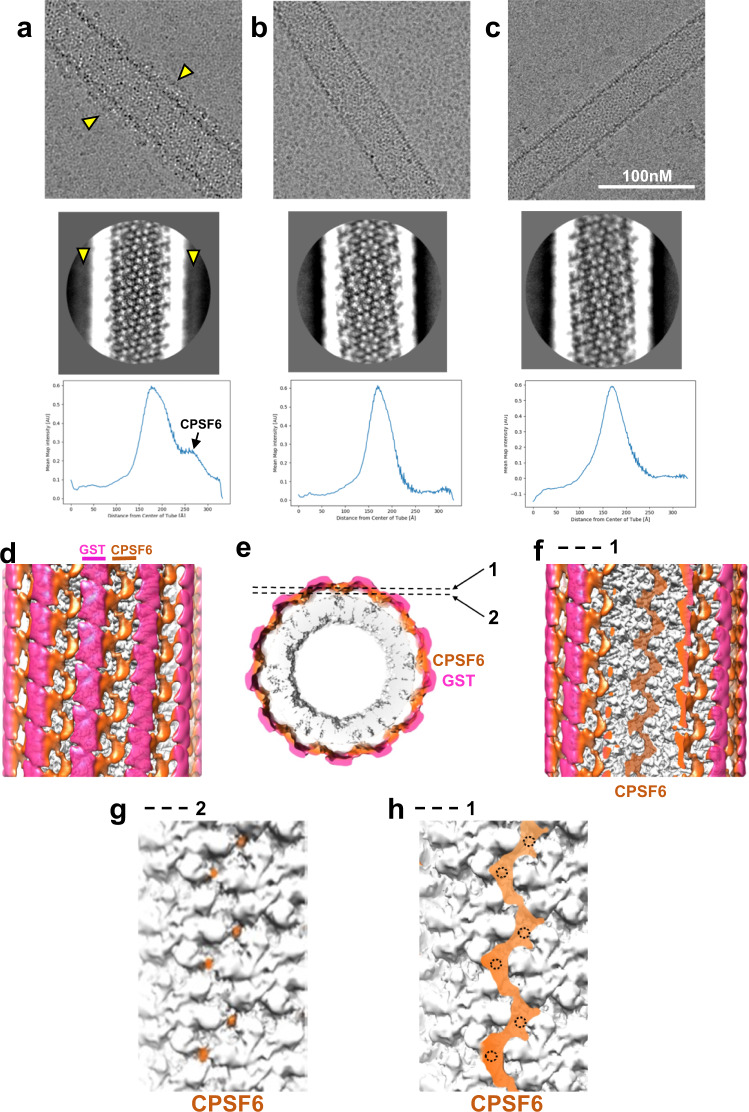
Fig. 5. Cryo-EM analysis of CPSF6(LCR-FG-LCR) binding to IP6-stabilized CA tubes.
Images of CA(A92E) tubes in the presence of WT GST-CPSF6261-358 (a); GST-CPSF6261-358(ΔFG), which contains LCR sequences but lacks the CA binding FG residues (b); and GST-CPSF6/AD(FG-nonLCR), which contains the CA binding 15-mer FG peptide but where flanking LCRs are replaced with nonLCR sequences from ADD2 (c). Partially ordered additional density (indicated by yellow arrow heads) along the surface of CA nanotubes was consistently observed in CA + WT GST-CPSF6261-358(LCR-FG-LCR) samples (a, top). This additional density was also evident in 2D class averages (a, middle, yellow arrow heads) and in 1D density profiles (a, bottom). In contrast, no additional density was apparent after addition of GST-CPSF6261-358(ΔFG) (b) or GST-CPSF6/AD(FG-nonLCR) (c) to CA nanotubes. The experiments were repeated 3 times independently with similar results. Front (d) and end (e) views of a cryo-EM map (~7.9 Å overall resolution) of a CA(A92E) nanotube in the presence of GST-CPSF6261-358(LCR-FG-LCR), filtered by local resolution and colored by radial distance from the center of the nanotube (CA in gray, CPSF6 in orange, GST dimers in semi-transparent magenta to help visualize CA and CPSF6 density). Front views of the same cryo-EM map, sliced at the two planes indicated in e, show continuous CPSF6 density arising from LCR interactions (f), as well as CPSF6 discrete contact points with the CA hexamer lattice (g) and their correspondence to continuous LCR density (h) (the doted circles mark the positions of CPSF6-CA contact points shown in g).

