
FIGURE 2.
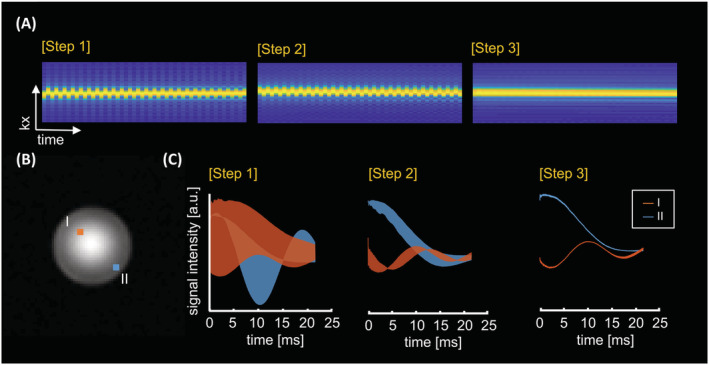
Spectral ghosting procedure for the echo‐planar spectroscopic imaging (EPSI) data via reconstruction steps (see Table 1). Gradient‐echo image (B) showed using a calibration phantom A (a sphere of 10 cm diameter) placed in the isocenter of the MR bore. (A) The effect on the acquired k‐t signal of the free induction decay (FID)‐EPSI readout for the phase‐corrected data by the following steps at the center location in (B). The alignment of k‐t space (A) is shown using the water reference signal, and (C) FID signals are presented at locations I and II in (B)