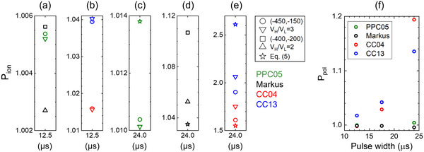
FIGURE 2.

(a–e) Ion recombination correction factors calculated for different chambers for the spread‐out Bragg peak (SOBP) beam. Circle and square symbols were calculated using Equation (4), triangle symbols were calculated using Equation (5), and star symbols were calculated using Equation (6). V H/V L = 2 in the legend indicates that Equation (5) was used with (‐400, ‐200) voltage pair for the Advanced Markus chamber. V H/V L = 3 in the legend indicates that Equation (5) was used with (‐450, ‐150) voltage pair. 25 (f) Polarity correction factor for four different chambers irradiated by a proton beam, at 2–150 Gy/s dose rate, generated by a synchrocyclotron 25
