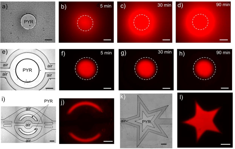
Fig. 2: Arbitrary control of hypoxic regions in hybrid microfluidic devices.
a) A brightfield image of a device where a circular opening in NOA is not flanked by air channels. b-d) Oxygen sensing dye was impregnated into the microfluidic device and was used to monitor hypoxic one over time. As can be seen from these images, without a supply of air from auxiliary channels, hypoxic zone spreads over the course of 1.5 h. e) A brightfield image of a device where circular opening in NOA mask is flanked by the side air channels. f-h) Time-lapse images of oxygen sensing fluorescence dye over the course of 1.5 h. As seen from these images, presence of air supply channel makes hypoxic zone stable. i) A brightfield image of the device used to generate two half-moon hypoxic zones. f) Corresponding fluorescence signal from the same device after 30 min of hypoxia. k) A brightfield image of a device used to generate a star-shaped hypoxic zone. l) Corresponding fluorescence image from the same device after 30min of hypoxia. The scale bars are 500μm in all figures.

