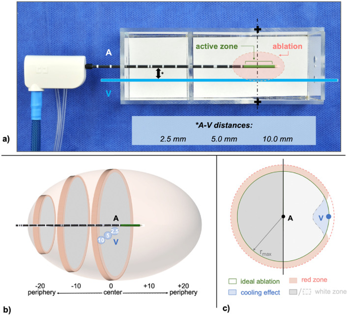
Figure 4.
(a) Experimental setup using a custom-made aiming device allowing exact positioning of the microwave antenna (A) and glass tube, which simulated a natural vessel (V). Three different antenna to vessel (A–V) distances (*) were evaluated. All ablations were initially cut at the largest cross-sectional area (+) which is expected at the centre of the active zone of the microwave antenna. (b) Ablations were then bisected every 2 mm from the ablation centre (0). Each ablation half could be divided into a maximum of ten slices (− 20/+ 20). (c) Only the ablation half containing the vessel (V) was used for a quantitative analysis. Cooling effects were determined by subtracting the actual ablation area from an idealized ablation, which was calculated with the maximum ablation radius (rmax).

