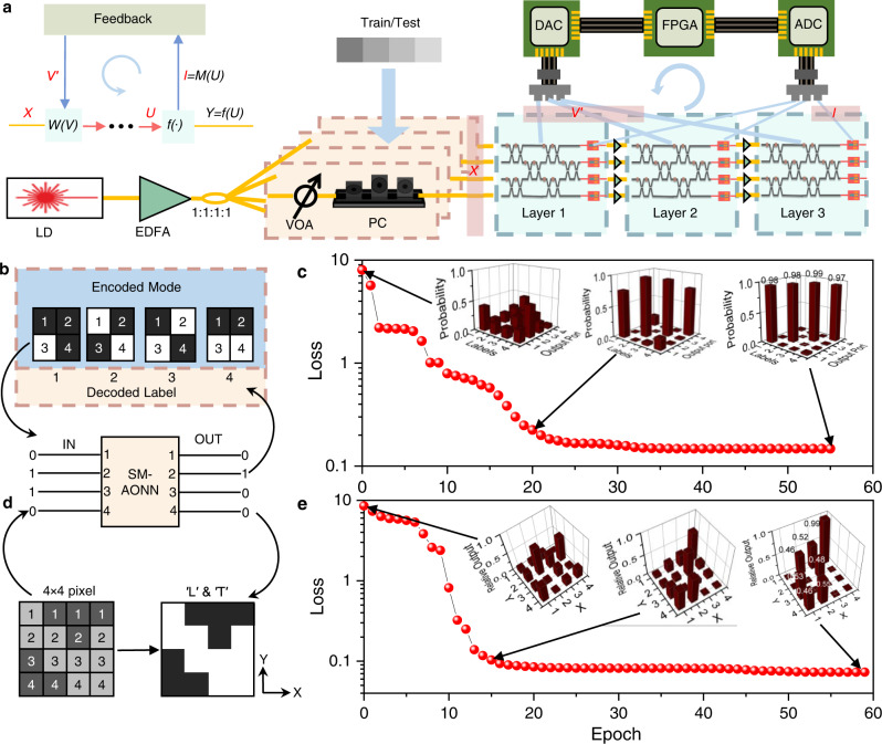
Fig. 4. Training and results of three-layer neural networks.
a The set-up diagram of training. The panel on the left side represents the data flow during training, where W(V), f (∙) are linear and nonlinear operations, respectively. X, Y are the input of the first layer and the output of the last layer, respectively. U and I are the optical input and electrical output of the last layer of AONU, respectively. V is the voltage that controls the weighting. LD, Laser. EDFA, Erbium-Doped Fiber Amplifier. VOA, Variable Optical Attenuator. PC, Polarization Controller. b Introduction of the classification task. Four modes are utilized for simplified classification tasks. The classified patterns are represented by 4 × 1 vectors. Black pixel is represented by ′1′ and input, while white is ′0′ and no input. The task is to train the neural network so that all modes are output only at their labeled ports. c The results of the classification task. The insets are the probabilities of each mode output from the four ports. d Introduction of the semantic segmentation task. The input in the dark gray area is set to 0.9 and the output is 1. The input in the light gray area is set to 0.1 and the output is 0. e The results of the semantic segmentation task. The insets are the relative outputs of 16 pixels.

