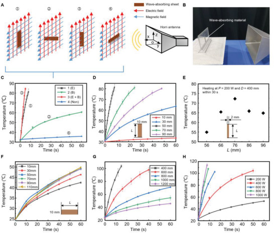
Figure 2.

Wave‐absorbing sheets under the microwave. A) Schematic showing poses of the sheet in the microwave field with the serial numbers labeled on the top. B) Layout of the testing platform. C) The experimental results show the heating effect of the wave‐absorbing sheet with different poses in the microwave field. D) Temperature increases in the sheet with different L values (insets) at pose 1, where P = 700 W and D = 400 mm. E) Temperature versus the length L of a 2 mm width slender microwave‐absorbing material after heating 30 s in microwaves (P = 200 W and D = 400 mm). Error bars indicate the SD for n = 3, where n is the number of groups of experimental data. F) Temperature rise in the sheet with different L values (insets) at pose 2, where P = 700 W and D = 400 mm. G,H) The temperature rise in the sheet at pose 1 under different transmitting powers P and different distances D between the wave‐absorbing sheet (50 mm × 10 mm) and the wave port. Error bars in (C, D, and F to H) indicate the SD for n = 6.
