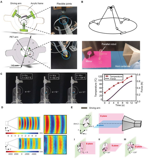
Figure 3.

Parallel robot controlled by microwaves. A) Schematic showing a parallel robot composed of three sections: three driving arms, an acrylic frame, and a PET arm. The PET arm has six flexible joints (right). B) Kinematical diagram of the parallel robot (top) and the location of the robot relative to the horn antenna (bottom). C) Sequence of images showing the characteristics of the driving arm under microwave irradiation (left) and the relationship between temperature and force (right). D) Simulation results of the magnetic (top) and electric (bottom) field radiated from a horn antenna using COMSOL. E) Schematic diagram of controlling the parallel robot via tuning the direction of polarization.
