
Figure 1.
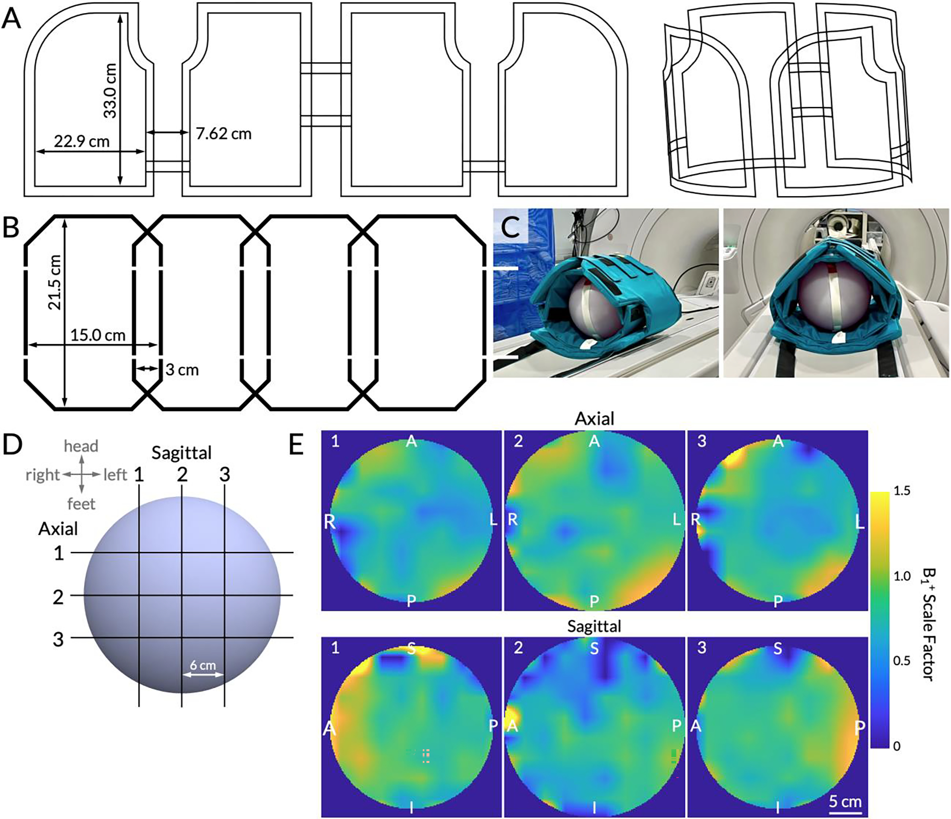
(A) Schematic conductor paths of the 13C volumetric transmitter, shown flat and in 3D. (B) Schematic conductor paths of the 13C receiver array. One of two identical 4-channel arrays is shown. (C) The coil setup using a 27.8 cm wide spherical dimethyl silicon phantom for Bloch-Siegert B1+ mapping. The inner vest is the 8-channel receiver array and the outer vest is the transmitter. (D) A schematic of the multi-slice B1+ maps. Three slices were acquired in the sagittal and axial planes with a 6 cm center-to-center separation. The slice numbers correspond to the B1+ maps (interpolated for display) shown in (E). Right/Left, Anterior/Posterior, and Superior/Inferior labels are displayed on the edges. The adjacent color bar shows the B1+ scale factor ranging from 0 to 1.5, with 1.0 indicating transmit power that matches the prescribed value.