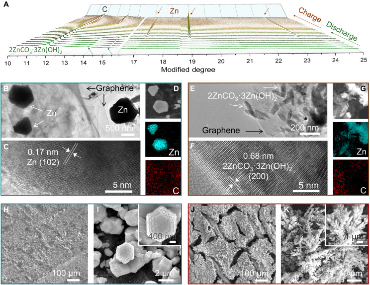
Fig. 4. Morphologies of the ZZG anode after cycling in 2 M K2CO3 electrolyte.
(A) In-situ synchrotron XRD patterns of the 2ZnCO3·3Zn(OH)2 anode during the discharge/charge process. (B to D) TEM and HRTEM images and energy-dispersive x-ray (EDX) mapping of the ZZG electrode after discharge. (E to G) TEM and HRTEM images and EDX mapping of the ZZG electrode after charge. (H and I) Top-view SEM images of the ZZG electrode after 3500 cycles. (J and K) Top-view SEM images of the metallic Zn electrode after 50 cycles in 6 M KOH with a saturated ZnO electrolyte.

