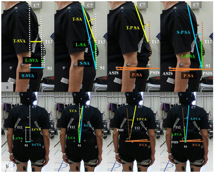
Figure 2.
(a) Sagittal parameters: the dotted white line indicates a perpendicular line to the floor. The dotted brown line indicates the perpendicular line to the surface created from the two ASIS and two PSIS points (pelvic surface). SVA was defined by the sagittal distance between C7–T12 (T–SVA), T12–S1 (L–SVA), and C7–S1(S–SVA). SA was defined by the sagittal angle of C7–T12 line (T-SA), T12–S1 line (L-SA), and C7–S1 line (S-SA) from the perpendicular line. PSA was defined by the sagittal angle between the floor and the pelvic surface. T-PSA, L-PSA, and S-PSA were defined by the sagittal angle of C7–T12 line (T-P SA), T12–S1 line (L-P SA), and C7–S1 line (S-P SA) from the perpendicular line to the pelvic surface; (b) coronal parameters: the dotted white line indicates a perpendicular line to the floor. The dotted brown line indicates the perpendicular line to the surface created from the two ASIS and two PSIS points (pelvic surface). CVA was defined by the coronal distance between C7–T12 (T-CVA), T12–S1 (L-CVA), and C7–S1 (S-CVA). CA was defined by the coronal angle of C7–T12 line (T-CA), T12–S1 line (L-CA), and C7–S1 line (S-CA) from the perpendicular line. PCA was defined by the coronal angle between the floor and the pelvic surface. T-P CA, L-P CA, and S-P CA were defined by the sagittal angle of C7–T12 line (T-P SA), T12–S1 line (L-P SA), and C7–S1 line (S-P SA) from the perpendicular line to the pelvic surface. (T), thoracic; (L), lumbar; (S), whole spinal; SVA, sagittal vertical axis; SA, sagittal angle; P SA, pelvic sagittal angle; ASIS, anterior superior iliac spine; PSIS, posterior superior iliac spine.

