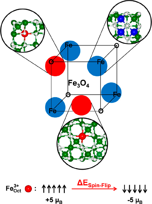
Figure 1.

Structural scheme of the magnetite cubic NP. The red circles indicate the corner and the surface portion where the spin-flip process, schematized at the bottom of the figure, is investigated. The blue circles indicate the corners involved in the reconstruction process. The ball-and-stick insets show the details of the surroundings of Fe atoms that are involved in the spin-flip (red beads, which are FeOct3+6c-(3) in the corner and FeOct5c-(5) on the flat surface, according to the labels used in Figure S1 and in ref (32)) and reconstruction process (blue beads). The white and green beads represent O and Fe.
