Fig. 7.
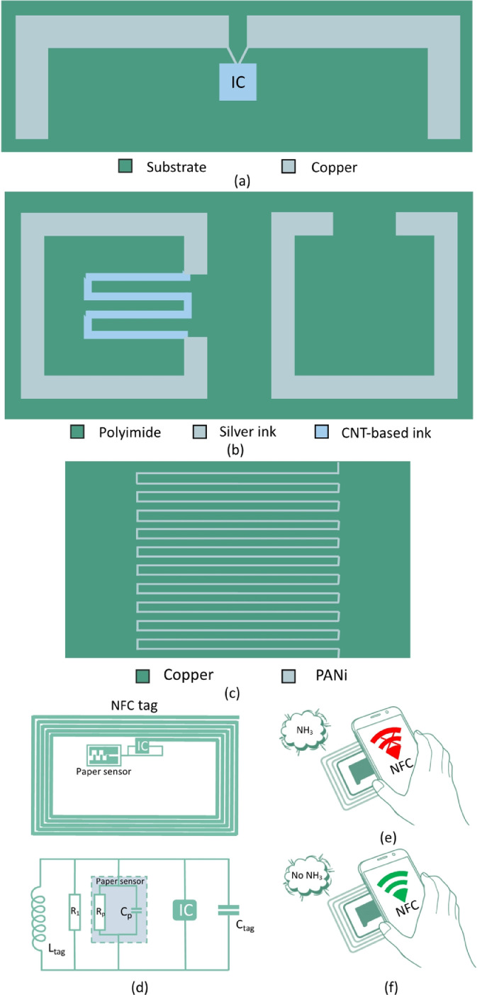
(a) The layout of pressure monitoring UHF tag (Li et al., 2009). (b) The layout of two SRRs in different polarization directions(Vena et al., 2013). (c) Schematic of the Inductor-Capacitor (LC) resonant tanks (Karuppuswami et al., 2020). (d) The schematic of the NFC tag is modified by PEGS. Once a certain concentration of ammonia is present, communication between the reader and the tag will be disrupted. The resistor R1 is used to adjust the tag gas sensing concentration threshold at which the tag stops working. (e) The tag responded when there was no ammonia in the box. (f) Smartphones cannot detect NFC tags when ammonia is present (Barandun et al., 2019).

