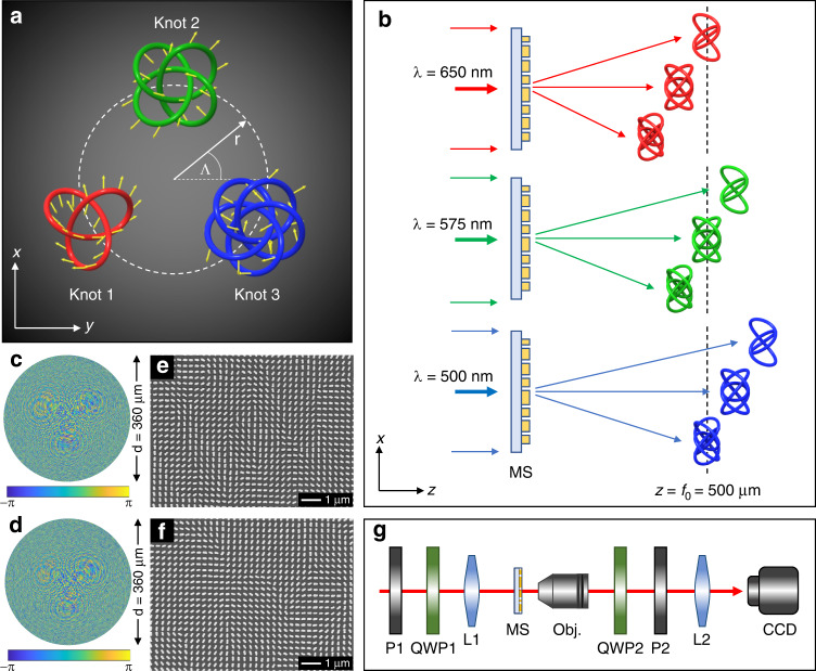
Fig. 2. Polarization knots arrangement, color-selective mechanism, SEM images of fabricated samples, and schematic of the experimental setup.
a The arrangement of the 3D polarization knots. The polarization direction of any given point is denoted with yellow arrows. b Color-selective mechanism. The locations of three different 3D knots are given upon the illumination of the incident light at λ = 650 nm (top), λ = 575 nm (middle), and λ = 500 nm (bottom), respectively. The observation region is defined by the two planes: z = 485 μm and z = 515 μm. The plane z = 500 μm is the middle plane of the observation region. Only one 3D polarization knot is obtained for a single incident wavelength; thus, the color-selective functionality is realized. c and d are the desired phase profiles for the two metadevices that can respectively generate multiple polarization knots and color-selective polarization knots in the same observation region. The corresponding scanning electron microscope (SEM) images of the fabricated metasurface devices are shown in (e) and (f), respectively. g Schematic of the experimental setup for characterizing the developed metadevices. P1 and P2: polarizers, QWP1 and QWP2: quarter wave plates, L1: convex lens (f = 15 cm), MS: metasurface device, Obj.: ×20 objective lens, L2: convex lens (f = 10 cm), CCD: charge-coupled device

