Figure 3.
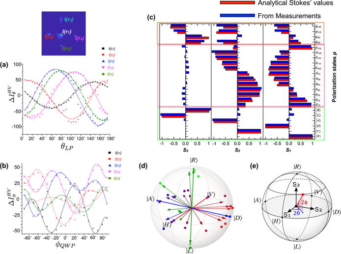
Using the intensity of the diffracted spots to extract the Stokes parameters and comparing with analytical Stokes’ values, (a) difference in intensities, ΔIθHV, of the five diffraction spots for all linear polarization states, θLP; (b) difference in the intensities of the five spots, ΔIϕ, for all elliptical polarization states corresponding to the QWP angle ϕQWP = ϕ/2 with the HWP maintained at 22.5°. The dots are experimentally measured values, while the lines are polynomial fits to serve as a guide to the eye. (c) Comparison of the experimental Stokes parameters for various polarization states obtained using the metasurface matrix (blue) and analytical Stokes’ values (red). The degenerate polarization states are highlighted in green, the linear polarizations in pink, and the elliptical polarizations in brown. (d) Representation as points on the Poincaré sphere of some of the input states (arrows) and the corresponding states experimentally identified by the metasurface (large dots) from results shown in (a–c). The small dots represent the six degenerate polarization states. These measurements have an average fidelity of 99.27 ± 0.86%. (e) Illustration of the Stokes parameters’ orientations along with the azimuth and ellipticity angles, 2θ and 2ϕ, respectively.

