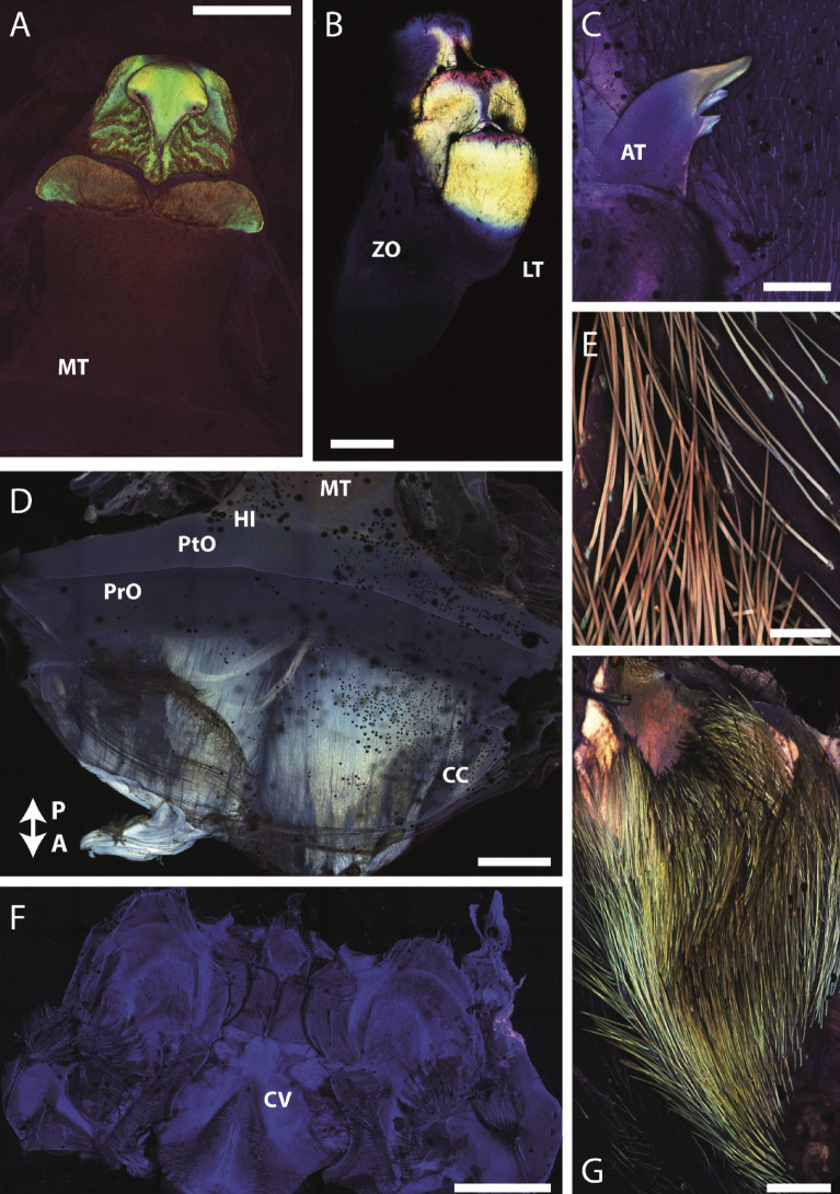
Figure 4.
CLSM images of the components of the gastric mill. Comparison of colors is only possible within each individual image, as they were taken individually. (A) Medial tooth. (B) Lateral tooth. (C) Accessory tooth. (D) Basis of medial tooth and cardiac chamber. The arrow points in the anterior and posterior direction. (E). Setae with high magnification. (F) Cardiopyloric valve and surrounding structures. (G) Setae and surrounding membrane. A anterior, AT accessory tooth, CC cardiac chamber, CV cardiopyloric valve, HI hinge of medial tooth, LT lateral tooth, MT medial tooth, P posterior, PrO prepterocardiac ossicle, PtO pterocardiac ossicle, ZO zygocardiac ossicle. Scale bars: A, 750 µm; B, 200 µm; C, 400 µm; D, 750 µm; E, 20 µm; F, 1500 µm; G, 100 µm.

