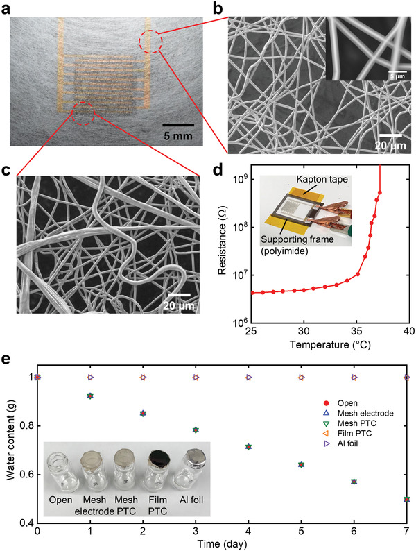
Figure 5.

Thermal and gas‐permeable characteristics of the thermistor with all‐mesh structures. a) A photograph of the mesh thermistor on a mesh substrate. b) SEM image of the mesh substrate. Inset: a magnified image of the parylene‐coated mesh electrode at an acceleration voltage of 15 kV. c) SEM image of the parylene‐coated composite fibers on the mesh substrate. d) Change in the resistance of the thermistor with all‐mesh structures as a function of temperature. Inset: a photograph of the fiber‐type thermistor on the mesh substrate with a supporting frame during measurement. e) The subsequent water weight loss for each sample. Inset: a photograph of samples.
