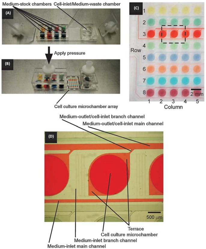
Figure 5.
Schematic diagram of a Microfluidic chip driven by pressure: (A) Eight different dyes are injected into the Microfluidic chip. (B) Pressure is applied by venting from the outside through a sterile ventilation filter, with the dashed line indicating the enlarged area in (C). (C) Microscopic photograph of the Microfluidic chip, with the dashed square indicating the expanded region in (D). (D) Three colors indicate three different microstructures. The image from [42], Copyright 2008, Wiley.

