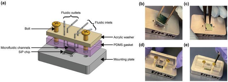
Figure 6.
(a) Schematic and (b–e) photos of microfluidic and photonic chip assembly for fluidic testing. (b) The chip is placed on the mounting plate, (c) the chip is positioned into the machined recess of the mounting plate, (d) bolts are threaded through the bolt holes of the acrylic washer and poly(dimethylsiloxane) (PDMS) gasket and aligned to the threaded holes in the mounting plate, and (e) bolts are screwed into place to align and seal the fluidics against the photonic chip.

