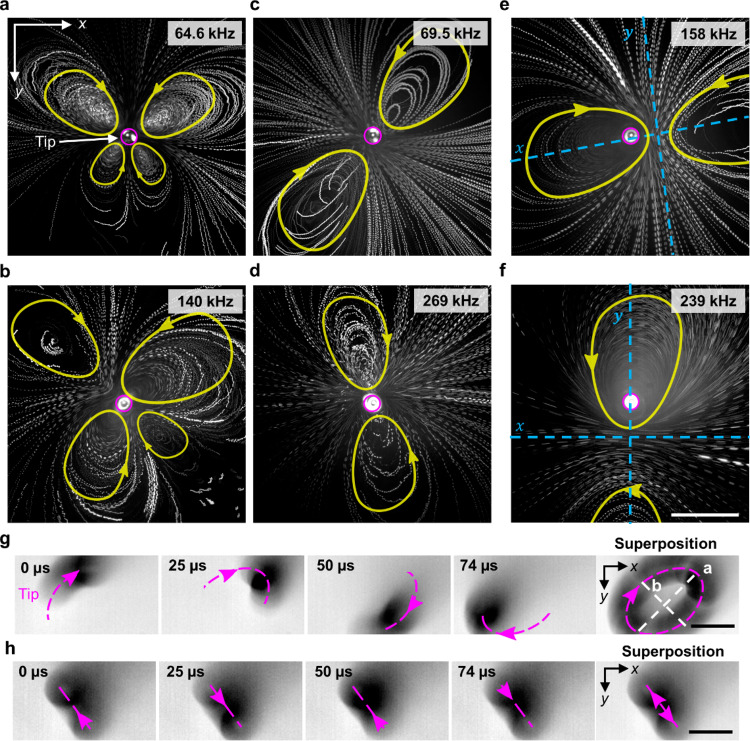
Fig. 3. Frequency-specific vortices or streaming produced by the tip of the acoustofluidic device in water containing tracer particles.
The acoustofluidic device produced steady 3D vortex flow patterns comprised of counter-rotating vortices (The pink circle represents the capillary tip position and yellow geometry represents the direction and path of motion of particles.) (see Supplementary Movie 4): a butterfly-like pattern of four vortices at a 64.6 kHz and b 158 kHz; a pair symmetric about the tip at c 69.5 and d 269 kHz; and a pair ~100 µm off-centre from the tip at e 69.5 kHz and f 269 kHz. The direction of flow is marked with yellow arrows, and the capillary tip indicated by a magenta circle. The symmetry axis is indicated in blue for images where the capillary tip does not represent the centre of symmetry. Dotted magenta lines indicate tip oscillation of the acoustofluidic device (see Supplementary Movie 5), which undergoes g elliptical motion at excitation frequency 6.8 kHz and amplitude 20 VPP and h translational motion at 7.8 kHz and 20 VPP. Scale bars: 50 µm.

