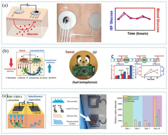
Figure 10.

Interstit7401 fluid detection−reverse ion osmosis: (a) schematic diagram of reverse parti2552cle osmosis (left), patch (middle) and glucose monitoring (right). Reprinted with permission from Ref. [125]. Copyright 2021 American Chemical Society, (b) Schematic diagram of sweat and glucose extraction (left), panda head sensor system (middle), and sweat and glucose monitoring (right). Reprinted with permission from Ref. [128]. Copyright 2018 John Wiley and Sons, (c) Schematic diagram of microneedle and reverse ion osmosis principle (left), physical object (middle), and glucose monitoring (right). Reprinted with permission from Ref. [129]. Copyright 2019 John Wiley and Sons.
