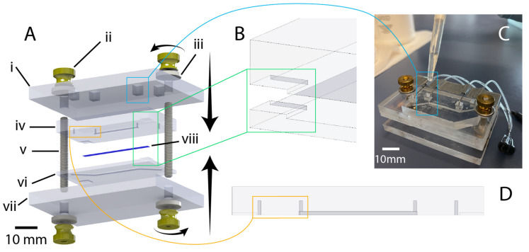
Figure 4.
Illustration of chip design and highlighting of critical features. (A) exploded view of chip components (created using SolidWorks): i: 1/4-inch-thick acrylic top clamp, ii: 8–32 brass flanged thumb nut, iii: 8–32 oversized washer, iv: PDMS chip (top half), v: 8–32 threaded rod (1.5” length), vi: PDMS chip (bottom half), vii: 1/4-inch thick acrylic bottom clamp, viii: PET membrane. (B) illustration of corner alignment features to assist manual mating of chip halves during bonding. (C) Illustration of liquid-PDMS reinforcement of fluidic port seal via pipetting of uncured PDMS into top-clamp cutouts. (D) Highlighting of punch guides to assist in the accurate positioning and clear formation of manually punched through-holes for fluidic connection.

