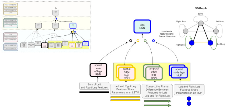
Figure 4.
Leg nodeRNN implementation details. This example shows how the input is represented for the leg node of the graph. The edges are defined in edgeRNNs as spatial and temporal information based on the semantics of the ST-Graph in Figure 2. (The model architecture and ST-Graph shown is greyed-out to zoom in on the the leg.) The three edgeRNN modules in the yellow denote parameter sharing occurring in the network between the left and right leg. For example, the spatial edge legs’ RNN will have one set of weights for both the left and right leg inputs. This introduces spatial awareness to the network while also compressing the size of the network.

