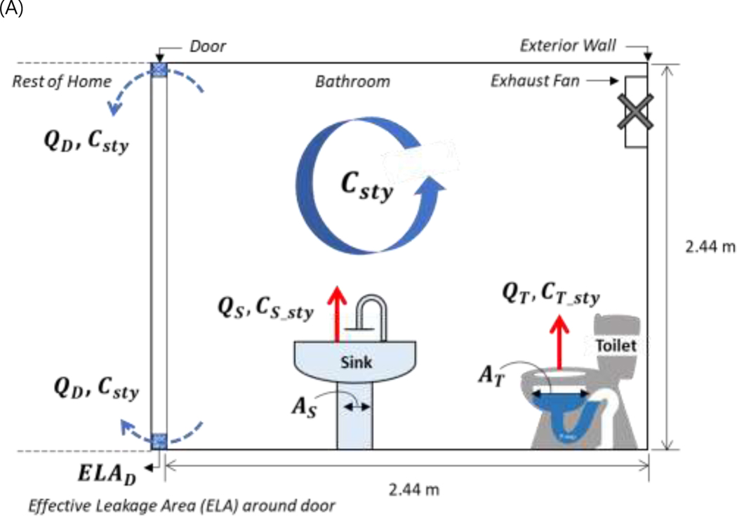
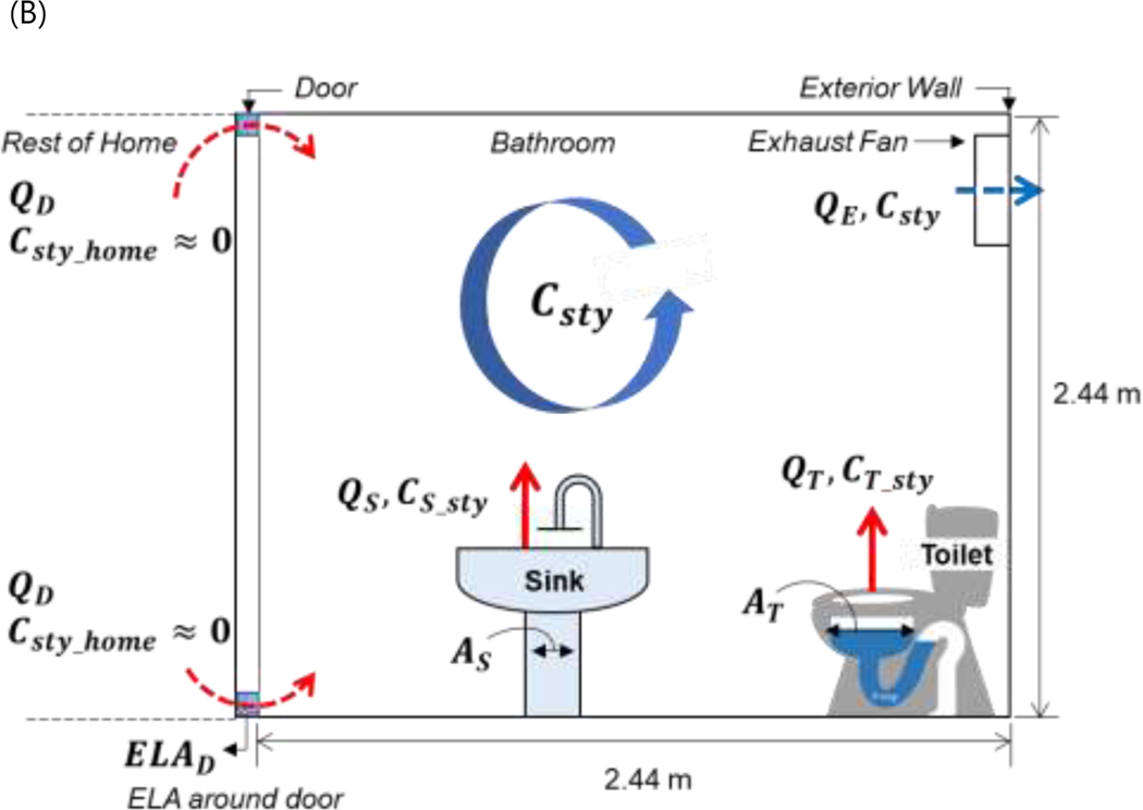
Figure 3.
Schematic of bathroom model with the location of the sink, toilet, and bathroom exhaust fan noted: (A) non-ventilation condition (exhaust fan off) and (B) ventilation condition (exhaust fan on). The diagram is a single-cell CSTR model; the arrows represent the airflow pathways. Supply and return vents for a home mechanical HVAC system are not considered.


