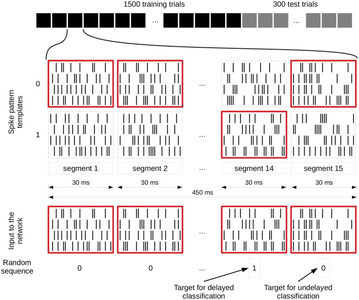
Figure 3.
Input generation for spike pattern based tasks. The first row shows the different trials of an experiment and the spike patterns below that represent a zero or one value for each segment of a single trial. These spike pattern templates are identical for all trials. The spike patterns at the bottom are chosen based on and therefore represent the randomly generated sequence of zeros and ones underneath, which also define the target for the readout training (value of segment 14 for delayed classification and segment 15 for the undelayed classification). We give a jittered version of these spike trains to the network (jittering is not shown). C.f. Figure 4, original publication (Häusler and Maass, 2007).

