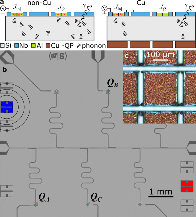
Fig. 1. Phonon-mediated QP poisoning and device layout.

a Schematic showing QP/phonon injection, γ impact, phonon propagation in substrate, and pair breaking in qubit junctions with and without Cu. b Optical micrograph of device layer. Qubits (QA,B,C) are colored green. Junctions used to inject QPs into the Cu (non-Cu) chip are highlighted in blue (red); concentric rings represent propagating phonons. c Optical micrograph of Cu islands on back side of Cu chip.
