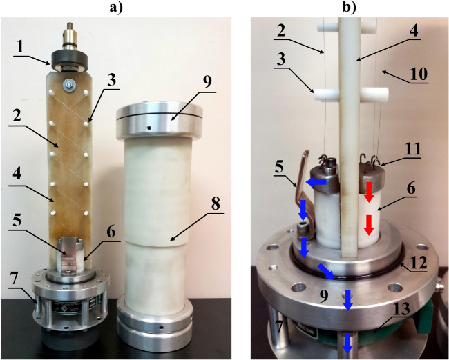
Figure 11.
Photographs of the TSFF laboratory model: view from the side of the forming stage and commutation spark gap (a) and a profile with a close-up view of the commutation spark gap structure (b): 1—quick mounting system for fusible elements, 2—forming stage fusible elements, 3—insulating supports, 4—fuse compartment insulating partition, 5—CSG adjustable electrode, 6—bushing insulator and support for lower internal fitting of fusible elements, 7—external fuse cage with an integrated current measuring transducer for measuring fuse current components, 8—insulating tube of the fuse compartment, 9—external fuse fitting, 10—preparatory stage fusible elements, 11—lower internal fittings with hooks, 12—gas seal of the fuse compartment, 13—broadband pulse current measuring transducer. The approximate current flow path of the preparatory stage is marked with red arrows, while the blue arrows indicate the forming stage current flow path.

