Figure 2.

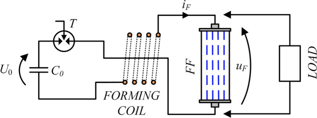
Schematic diagram of the fuse-based high-power pulse forming system supplied by pulse capacitor bank: C0—pulse capacitor bank charged to voltage U0; T—trigatron (triggered spark gap), iF, uF—forming fuse current and voltage.

Schematic diagram of the fuse-based high-power pulse forming system supplied by pulse capacitor bank: C0—pulse capacitor bank charged to voltage U0; T—trigatron (triggered spark gap), iF, uF—forming fuse current and voltage.